Support Center
- Configuring Network Service ACLs
- Configuring ACLs for Deep Packet Inspection
- Configuring ACLs on APs for Website Content Classification
- Configuring User Roles for AP Clients

Configuring Role Derivation Rules for AP Clients
- Configuring Firewall Parameters for Wireless Network Protection
- Configuring Custom Redirection URLs for Clients
- Configuring Firewall Parameters for Inbound Traffic
- Enabling ALG Protocols on Instant APs
Aruba Central allows you to configure role and VLAN Virtual Local Area Network. In computer networking, a single Layer 2 network may be partitioned to create multiple distinct broadcast domains, which are mutually isolated so that packets can only pass between them through one or more routers; such a domain is referred to as a Virtual Local Area Network, Virtual LAN, or VLAN. derivation-rules. You can configure these rules to assign a user role or VLAN to the clients connecting to an SSID Service Set Identifier. SSID is a name given to a WLAN and is used by the client to access a WLAN network. or a wired profile.
Creating a Role Derivation Rule
You can configure rules for determining the role that is assigned for each authenticated client.
When creating more than one role assignment rule, the first matching rule in the rule list is applied.
To create a role assignment rule, complete the following steps:
1. In the Network Operations app, set the filter to a group that contains at least one AP.
The dashboard context for the group is displayed.
2. Under Manage , click Devices > Access Points .
A list of access points is displayed in the List view.
3. Click the Config icon.
The tabs to configure the access points are displayed.
4. Click the WLANs tab.
The WLANs Wireless Local Area Network. WLAN is a 802.11 standards-based LAN that the users access through a wireless connection. details page is displayed.
5. In the Wireless SSIDs table, select a network profile and then click the edit icon.
6. Click the Access tab.
7. Under Access rules , select Role Based to enable access based on user roles.
8. Under Role Assignment Rules , click + Add Role Assignment . In New Role Assignment Rule , define a match method by which the string in Operand is matched with the attribute value returned by the authentication server.
9. Select the attribute from the Attribute list that the rule it matches against. The list of supported attributes includes RADIUS Remote Authentication Dial-In User Service. An Industry-standard network access protocol for remote authentication. It allows authentication, authorization, and accounting of remote users who want to access network resources. attributes, dhcp-option, dot1x-authentication-type, mac-address, and mac-address-and-dhcp-options.
10. Select the operator from the Operator list. The following types of operators are supported:
contains —The rule is applied only if the attribute value contains the string specified in Operand .
Is the role —The rule is applied if the attribute value is the role.
equals —The rule is applied only if the attribute value is equal to the string specified in Operand .
not-equals —The rule is applied only if the attribute value is not equal to the string specified in Operand .
starts-with —The rule is applied only if the attribute value starts with the string specified in Operand .
ends-with —The rule is applied only if the attribute value ends with string specified in Operand .
matches-regular-expression —The rule is applied only if the attribute value matches the regular expression pattern specified in Operand . This operator is available only if the mac-address-and-dhcp-options attribute is selected in the Attribute list. The mac-address-and-dhcp-options attribute and matches-regular-expression are applicable only for WLAN clients.
11. Enter the string to match in the String box.
12. Select the appropriate role from the Role list.
13. Click Save .
Configuring VLAN Assignment Rule
To configure VLAN assignment rules for an SSID profile:
The WLANs details page is displayed.
7. Select the access rule from Access rules .
8. In the Access Rules For Selected Roles , click + Add Rule to add a new rule. The Access Rule page is displayed.
The VLAN Assignment option is also listed in the Access Rule page when you create or edit a rule for wired port profiles in the Ports > Create a New Network > Access tab.
9. From the Rule Type drop-down list, select VLAN Assignment option.
10. Enter the VLAN ID in the VLAN ID field under Service section. Alternatively, you can select the VLAN ID or the VLAN name from the drop-down list provided next to the VLAN ID field.
11. Click Save .
Configuring VLAN Derivation Rules
The users are assigned to a VLAN based on the attributes returned by the RADIUS server after users authenticate.
To configure VLAN derivation rules for an SSID profile:
6. Under VLANs , select Dynamic under Client VLAN Assignment .
7. Click + Add Rule to create a VLAN assignment rule. The New VLAN Assignment Rule window is displayed. In this window, you can define a match method by which the string in Operand is matched with the attribute values returned by the authentication server.
8. Select an attribute from the Attribute list.
9. Select an operator from the Operator list. The following types of operators are supported:
matches-regular-expression —The rule is applied only if the attribute value matches the regular expression pattern specified in Operand . This operator is available only if the mac-address-and-dhcp-options attribute is selected in the Attribute list. The mac-address-and-dhcp-options attribute and matches-regular-expression are applicable only for the WLAN clients.
10. Enter the string to match in the String field.
11. Select the appropriate VLAN ID from VLAN . Ensure that all other required parameters are configured.
12. Click OK .

- PORTNOX CLOUD Unified Access Control Any Device. Any Data. Anywhere.
Zero Trust Network Access Control
- Cloud-native RADIUS Stand up Portnox’s cloud-native RADIUS is minutes.
- Passwordless authentication Leverage certificates for passwordless network authentication.
- Risk posture assessment Monitor the potential risk of every connected device.
- Compliance enforcement Automate device remediation & stay compliant 24/7.
- Explore Pricing

Zero Trust Conditional Access
- How does it work? Discover how to better secure your apps with Portnox.
- Passwordless authentication Bolster application access by going passwordless.
- 24/7 risk monitoring Ensure only trusted devices gain access to your apps.
- Automated remediation Automate device-based compliance enforcement.

Zero Trust Infrastructure Administration
- How does it work? Explore cloud-native TACACS+ from Portnox.
- Admin authentication Get started with simple, secure admin authentication.
- Access policy enforcement Make sure not just anyone can tinker with your infrastructure.
- Granular accounting Keep auditors at bay with cloud-native TACACS+.

Unified Zero Trust Security
- How does it work? Learn the ins and outs of the Portnox Cloud.
- Cloud-native RADIUS authentication Spin up our cloud-native RADIUS server in minutes.
- Passwordless application security Bolster application access by going passwordless.
- Zero trust network access control See and control access for every device across your network.
- Network device administration Keep auditors at bay with cloud-native TACACS+.

- Authentication
- Access Control
- Risk Monitoring
- Remediation
- IoT Security
- Guest Access
Applications
Infrastructure.
- Authorization
Integrations
- Case Studies
- Infographics
- Product Briefs
- White Papers
- Cloud Documentation
Compliance Center
Regulations, cybersecurity center.
- What is 802.1X? What are the benefits of NAC? How does zero trust work? Why go passwordless? What is IoT profiling? Explore All »
- Reseller Program
- Managed Services
- Become a Partner
- Register a Deal
- Get Started
Network Access Control , Network Security
Segmenting your network with dynamic vlan.

What is Dynamic VLAN?
VLANs (Virtual Local Area Networks) enable segmentation of the main organizational network. In practice, VLANs allow network administrators to keep devices and network resources separated despite being connected to the same physical network.
Dynamic VLAN assignment separates and isolates devices into different network segments based on the device or user authorization and their characteristics. The flow of traffic between those VLANs is governed by a firewall or another routing device which can then enforce specific network access rules.
Why Use Dynamic VLANs?
Segmenting the network is a security best practice, and in some cases is even a regulatory requirement – such as with PCI. Network segmentation is a measure that improves the effectiveness of all the current investments in other security tools, and can by itself help to prevent significant damage to critical organizational data across the network after a company has been breached.
Automating VLAN assignments and eliminating the need for manual intervention has historically been a challenge for network security teams. Today, automatic VLAN assignment is best implemented by the use of a RADIUS service, which functions as follows:
- A device connects to one of several the network access layers: wired ethernet switch or WiFi SSID
- The network access layer sends a request to the RADIUS server with the user’s credentials or certificates (using 802.1X)
- The RADIUS server sends a reply which contains attributes that provide the switch or access point with information on the device VLAN, result in properly VLAN assignment
Common Dynamic VLAN Assignment Use Cases
Network and security administrator most commonly encounter these use cases for dynamic VLAN assignment:
- The Sales & Marketing department does not need access to R&D resources, while R&D should not have access to the Finance Department resources. Using dynamic VLANs, each department will be placed in the correct VLAN with the required access.
- Devices that fail to authenticate due to wrong credentials or incorrect/expired certificate will be placed in a quarantine VLAN with internet access only.
- IP Phones using a dedicated voice VLAN and should be placed on that VLAN upon successful authentication.
- MAC bypass for devices that do not support 802.1X should be placed in their own dedicated VLAN.
- Devices that fail posture assessment (such as those without updated AntiVirus) should be placed in a quarantine VLAN with limited access.
- Employees connecting to one single WiFi SSID and get different access (VLANs) based on their authentication repository LDAP groups.
Dynamic VLAN Assignment with Portnox CLEAR
As mentioned earlier, the implementation of dynamic VLAN assignment has often been challenging for organizations since additional servers were needed on-site at the datacenter. This forced network teams to manage redundancies, complex configurations, and on-going maintenance.
To paint a clearer picture of this headache, consider this:
Take the case of connecting a new department, branch, or merely onboarding a lot of new employees at once…this can cause a surge in demand, which will in turn cause the whole network to “shutdown,” thus not accepting anyone who tries to connect.
Portnox CLEAR is a network access control solution, deployed as a cloud service, that provides all the mentioned use cases and more. CLEAR simplifies the implementation process of dynamic VLAN assignment. CLEAR allows you to easily set-up a cloud RADIUS server in a single click, and integrate with various authentication repositories like on-premise Active Directory, Azure AD, GSuite, OKTA. Plus, you can enforce your own unique access control policy to dynamically assign users to their respective VLANs.
In addition to VLAN assignment based on credentials authorization, CLEAR also allows you to implement dynamic VLAN assignment based on risk violation. This means that even devices that have authenticated successfully to the wired or wireless network can be dynamically moved to a dedicated VLAN if they fall out of compliance.

In the diagram above:
- PCs are dynamically assigned to the VLAN based on their credentials/certificate.
- IP Phones are assigned to the VOIP VLAN.
- Printers are assigned to the printers VLAN.
- Guests devices assigned to the internet-only access/quarantine VLAN.
How it Works – Setting up Dynamic VLAN Assignment in Portnox CLEAR:
1. enable cloud radius.
In the CLEAR portal, create your one-click cloud RADIUS server: Go to Settings > Services > CLEAR RADIUS Service , and add your RADIUS service instance:

And point your network equipment: wired switches and/or wireless controllers to work with these CLEAR Radius service details.
2. Creating an Access Control Policy – Dynamic VLAN Assignment:
In Policies > Access Control Policies , add or edit your existing access control policy, select the required access layer and add the correct VLAN ID or VLAN name for each event you want to create dynamic VLAN assignment for: successful authentication, authentication violation, risk assessment, blocked by admin. Then, map the access control policy to the relevant groups and users.

Related Reading
Decoding Unified Access Control: A Comprehensive Guide

Tackling Device Access with Custom TACACS+
Securing Your Network: Combat Insider Threats with Network Access Control
Try portnox cloud for free today.
Gain access to all of Portnox's powerful zero trust access control free capabilities for 30 days!
Privacy Overview
Portnox debuts passwordless zero trust conditional access for applications
How to Set Up a VLAN in 12 Steps: Creation & Configuration
Shelby Hiter
eSecurity Planet content and product recommendations are editorially independent. We may make money when you click on links to our partners. Learn More .
Setting up a virtual local area network (VLAN) can be a complicated process, especially if you’re operating a large enterprise network, a network with legacy or hybrid architectures, or a network with specific workloads that require additional security and regulatory compliance safeguards.
Each VLAN configuration process will look a little different, depending on the specifications you bring to the table, and some of these steps — particularly steps five through eight — may be completed simultaneously, in a slightly different order, or even in a more automated fashion if you choose to set up a dynamic VLAN.
Still, in general, your network stands the best chance of success if you complete the following 12 VLAN configuration steps and document your processes, strategies, and requirements along the way.
Table of Contents
1. Brainstorm VLAN Groupings
In a traditional local area network with no virtualized barriers, all devices and network components communicate and share information with each other; you’re likely setting up a VLAN in the first place because this foundational setup is too loose for your requirements. But what are the ideal segments that will make your network function optimally and securely?
At this point in VLAN creation and configuration, it’s time to determine what VLAN groupings make the most sense for your network’s strategic complexities. Consider not only how many VLANs you’ll need but also the purpose each VLAN will serve and how they need to be set up to fulfill that purpose. While many organizations stick to more traditional boundaries like physical locations or departments, there may be more effective and secure ways for you to group and set up VLAN rules.
For example, if your company works closely with a third-party professional services firm that needs access to certain HR and security applications and data but not others, you could divide your VLANs based on which ones need looser versus stricter identity and access management controls. From there, determine which users and devices will align with and be assigned to each grouping.

2. Prepare Unique VLAN IDs
Every single VLAN you set up will need a unique VLAN identification number so you can segment network traffic to the appropriate places and keep documentation organized for multiple VLANs simultaneously. VLAN IDs are purely numeric and range from one to 4,095. While you don’t necessarily “need” these VLAN IDs to be operational yet, it’s a good idea to figure them out now so you can use them when labeling your network diagram in the next step.
3. Create a Logical Network Diagram or Map
Before you even begin setting up your VLANs and connecting devices and switches, the best way to ensure a successful VLAN network setup is to map out the specificities and relationships of your network with a network diagram. The labels and connections you illustrate at this stage of VLAN creation will give you the labels and organizational structure you need to keep track of all the devices, switches, routers, and other components necessary to fulfill your architectural plans.
Your team may choose to create this diagram manually or with tools that are already in your portfolio. However, a number of free and low-cost network diagramming tools specifically offer templates and icons that make it easier to illustrate the network you’re setting up, often with low-code/no-code interfaces and tools. If you’re interested in finding a network diagramming tool to make this step more efficient, consider investing in one of these top network diagram software and tooling solutions .

4. Optional: Purchase Additional Equipment
Based on the VLAN grouping requirements and design(s) you’ve developed in the previous three steps, you should have a clearer picture of any missing hardware or software that you need to purchase. Perhaps you have more VLAN groupings than you expected and need to bring in additional switches and routers. Or maybe your organization is growing quickly, and you want to purchase new switches with more ports for more devices. There’s also the possibility that you are moving from a primarily on-premises network setup to a hybrid or cloud setup that requires new software or third-party relationships.
Regardless of your new requirements, start by creating an inventory list of any networking equipment you currently own, including information about switch and router formats, configurations, port counts, speeds, and other details pertinent to VLAN setup. From there, make a separate list of the networking tools you’re missing, the cost of these missing tools, and any other specialized information that should be considered during the buying process.
5. Connect Network Devices to Appropriate Switch Ports
You should now connect VLAN servers, end-user devices, and other relevant network devices — as long as their IP addresses are already configured — to the switch ports that have been selected for the corresponding VLAN group. While individual devices, ports, switches, and routers have not yet necessarily been configured in their settings to align with a certain VLAN and function, you should still know which devices and network components have been set aside for which VLANs. If you’re unsure about the switch ports that should be connecting to each device, reference your network diagram (or go back to the network diagramming stage and create a more detailed diagram).
If you are opting to create a dynamic VLAN instead of a static VLAN, steps five through eight may look a little different for you. For example, you may spend these steps creating or identifying the appropriate rule-based protocols for your devices and setting up automation rules rather than manually connecting ports and devices to VLANs.
6. Configure Switch Ports
Now that your devices are connected to the correct switch ports, it’s time to configure the switch ports so they can perform according to their assigned functions. Many of your ports will simply need to be set up as access ports in the switch’s settings; an access port is a simple connection that allows devices to connect to only one VLAN. Access ports are most appropriate for devices and users that will not be using VLAN tagging or participating in inter-VLAN routing.
Trunk ports are also configured in a switch’s settings, but they are designed to manage higher bandwidth traffic and can manage traffic for more than one VLAN. Devices should only be connected to trunk ports if they have been authorized and configured for VLAN tagging and inter-VLAN routing. Before moving on to the next step, double-check that devices are connected to the correct type of switch port for their operational needs.
7. Set up VLAN Specifications via Network Switch Settings
All of the prework is done: It’s time to actually create the virtual local area networks you want through network switch settings. You’ll do this by accessing your network switch management interfaces and going to the section where you can create VLANs. Create the number of VLANs you determined were necessary in previous steps and assign them the unique VLAN IDs you selected in step two.
8. Assign Switch Ports to VLANs
Again, keep in mind that steps five through eight may go in a slightly different order, depending on your team and their preferences. So if you have not yet assigned switch ports to the appropriate VLAN, it’s time to do that now. Tagged ports (trunk ports) are likely already associated with the correct VLANs, but you should confirm that they are set up correctly at this time. For untagged ports (access ports), you’ll need to manually connect them to the correct VLAN. Remember, trunk ports can be associated with more than one VLAN, if appropriate.
9. Optional: Add VLAN Tags
VLAN tagging is the process through which VLAN network traffic is further segmented and specialized. When VLAN tags are in use, associated devices and ports automatically interact with devices and ports that share those same tags; however, tags also give network administrators the power to further direct traffic and support case-by-case inter-VLAN routing scenarios.
VLAN tagging is most appropriate for networks with complex traffic patterns and a diverse range of users, devices, and security permissions. If you choose to set up trunk ports with multiple VLANs running through them, as demonstrated in step six, you’ll need to make sure at least some of your VLANs receive tags so traffic doesn’t get muddled in trunk ports.
If you’re not sure if your network would benefit from VLAN tags, read this in-depth article on the topic to help you make your decision: Tagged vs. Untagged VLAN: When You Should Use Each .
10. Optional: Configure Inter-VLAN Routing
If your network requires VLAN-to-VLAN communication as a part of its regular operations, you’ll want to use the VLAN tags you set up in the previous step to direct inter-VLAN routing. While it sounds counterintuitive to open traffic flow between VLANs, many organizations choose to do this because the different layer at which routers operate makes it possible for them to still control what types of traffic flow across VLANs and when and how devices and users move from VLAN to VLAN. As part of the inter-VLAN configuration step, you may also need to set up or double-check your VLAN access controls, ensuring only approved users and devices can take advantage of inter-VLAN routing.
11. Quality-Test Your VLAN
Now that everything’s set up, it’s time to test network connectivity and performance. Make sure that all devices within the same VLAN are able to interact with each other and, conversely, that they are not able to reach devices in other VLANs. Ping and traceroute are both effective tools for testing VLAN connectivity and performance, but a number of other network security and management tools may be appropriate as well.
12. Document and Reassess VLAN Performance Periodically
Enterprise networks in particular frequently change as more devices and users, new hardware and software requirements, and new operational and security use cases arise. Network administrators and/or network security team members should maintain an up-to-date network diagram, equipment inventory, changelogs, and other configuration documentation so it’s easy to see what the network looks like now, if and where any vulnerabilities have reared their heads, and if any other changes are necessary to improve network performance. Each time you go through this process, update your documentation so you have a full history of the network and what you’ve done to maintain it.
Should You Use a Static VLAN or Dynamic VLAN?
Static and dynamic VLANs bring different advantages to network administrators, depending on the size, complexity, and requirements of their network. Below, we’ve explained how each type works and when you should use it.

Static VLAN
Static VLANs exist when network administrators manually connect network devices to physical switch ports and those devices receive their VLAN assignment based on that connection. If the device ever needs to be reassigned to a new VLAN, the network administrator would physically connect it to a new switch port that is already associated with that VLAN. In other words, a static VLAN is one in which switch ports are assigned to VLANs and devices are not assigned to VLANs; they receive their orders directly from the switch port they’re connected to.
This type of VLAN is best for smaller networks, or networks that change infrequently and include fewer VLAN segments because network administrators have to manually connect (and sometimes reconnect) devices to the right ports for them to work. With a larger network that’s changing frequently, this task alone could become a full-time job and riddled with errors. Static VLANs are most advantageous for network administrators who need an easy-to-setup VLAN with predictable infrastructure and limited authentication needs.
Dynamic VLAN
A dynamic VLAN is one in which devices are assigned to that VLAN on a dynamic and semi-automated basis. Specialized criteria determine which devices are assigned to which VLANs and when. These criteria may include specialized network access controls and protocols, VLAN membership policy servers (VMPS) and databases, or some other combination of servers and data-driven rules. With a dynamic VLAN, devices are assigned to VLANs while ports frequently are not assigned to particular VLANs; they are simply the conduit through which pre-assigned device traffic flows.
Dynamic VLANs are best for larger and more complex networks that need to maintain frequently changing authentication and usage rules. It’s a much more difficult implementation process when compared to static VLAN, but for more strenuous network rules and requirements, dynamic VLAN ultimately saves network professionals time in the long run, as they can simply update protocols and VMPS entries when new VLAN assignments are needed across multiple devices.
Bottom Line: The Importance of Preparation for Optimal VLAN Performance
While the actual process of setting up a VLAN can be as simple as updating network switch settings and connecting devices to VLAN switch ports, the strategy behind a successful VLAN setup can be much more daunting. You’ll need to consider any specialized security or compliance requirements, the different device types that need access, and the resources and monitoring it will take to set up and sustain an efficient VLAN.
All the steps listed above are crucial aspects of creating and configuring a sustainable VLAN network. But perhaps the most important step of all is documenting your thought process and your network architecture, especially as they change over time. Maintaining detailed documentation will help your existing network and security team members stay on top of the most pertinent network updates and issues while simultaneously ensuring that any future members of the team receive the foundational training necessary to successfully work in your VLAN ecosystem.
Read next: What Is Network Security? Definition, Threats & Protections
Get the Free Cybersecurity Newsletter
Strengthen your organization’s IT security defenses by keeping up to date on the latest cybersecurity news, solutions, and best practices.
Previous article
Next article

Subscribe to Cybersecurity Insider
Strengthen your organization’s IT security defenses by keeping abreast of the latest cybersecurity news, solutions, and best practices.
IT Security Resources
Vulnerability recap 4/1/24: cisco, fortinet & windows server updates.

What Is Data Loss Prevention (DLP)? Definition & How It Works

LastPass Review 2024: Features, Pricing, Pros & Cons

15 Best Encryption Software & Tools for 2024

Top Cybersecurity Companies
Top 10 cybersecurity companies.
- 1 Uniqkey – Business Password Manager
See full list
Get the Free Newsletter!
Subscribe to Cybersecurity Insider for top news, trends & analysis
Related Articles

Data Security Compliance: How to Comply with Security Laws

What Is Cross-Site Scripting (XSS)? Types, Risks & Prevention
- Docs »
- pfSense® software »
- Virtual LANs (VLANs)
- Give Feedback
VLAN Configuration 
This section covers how to configure VLANs in pfSense® software.
Console VLAN configuration 
VLANs can be configured at the console using the Assign Interfaces function. The following example shows how to configure two VLANs, ID 10 and 20 , with igb2 as the parent interface. The VLAN interfaces are assigned as OPT1 and OPT2 :
After a few seconds, the firewall settings will reload and the console menu will reload.
Web interface VLAN configuration 
In the system used for this example, WAN and LAN are assigned as igb1 and igb0 respectively. There is also an igb2 interface that will be used as the VLAN parent interface.
To configure VLANs in the firewall GUI:
Navigate to Interfaces > Assignments to view the interface list.
Click the VLANs tab.

Configure the VLAN as shown in Figure Edit VLAN .
The physical interface upon which this VLAN tag will be used. In this case, igb2
The VLAN ID number, in this case, 10
Leave at the default value, blank
Some text to identify the purpose of the VLAN, such as DMZ

Edit VLAN 
Click Save to return to the VLAN list, which now includes the newly added VLAN 10 .
Repeat the process to add additional VLANs, such as VLAN 20 . These can be seen in Figure VLAN list

VLAN list 
To assign the VLANs to interfaces:
Navigate to Interfaces > Assignments
Click the Interface Assignments tab
Select the VLAN to add from the Available Network Ports list, such as VLAN 10 on igb2 (DMZ)
Repeat the last two steps to assign VLAN 20 on igb2 (Phones)
When finished, the interfaces will look like Figure Interfaces list with VLANs

Interfaces list with VLANs 
The VLAN-based OPT interfaces behave as any other OPT interfaces do, which means they must be enabled, configured, have firewall rules added, and services like the DHCP Server will need to be configured if needed. See Interface Configuration Basics for more information on configuring optional interfaces.
How to Setup and Secure UniFi VLAN
When you have a UniFi Security Gateway or UniFi Dream Machine (UDM, UDM Pro) you can create different VLANs on your network. Virtual LANs (VLANs), allow you to divide your physical network into virtual networks, offering isolation, security, and scalability.
Now you might think, do I really need VLANs? But when guests are connecting to your home network, you probably don’t want them to have access to all your network devices. And if you have a smart home, then creating a separate VLAN might be a good idea. Because the security of IoT devices is not always as it should be.
In this article
So in this article, I will explain how to set up and secure VLANs in the UniFi Network Console.
Note This article is updated in dec 2023, using the latest UniFi Network version (8.0.x). It explains how to configure VLANs using VLAN Magic , Traffic Rules and/or Firewall Rules
Setup UniFi VLANs
Creating VLANs in UniFi exists out of a couple of steps because we not only have to create the different networks, but we also need to secure the VLANs. The “problem” with UniFi is that inter-VLAN traffic is allowed by default. So without any firewall rules, traffic from for example the guest VLAN can just access the main VLAN.
In this example, we will be creating 3 VLAN networks for:
- Guests – VLAN 20
- Cameras – VLAN 30
- IoT devices – VLAN 40
The guest VLAN is a bit different from the other VLANs because UniFi will automatically create the necessary firewall rules for the guest network. All you have to do is Isolate the network in the network settings.
So in the steps below, we will create the guest network, with the correct settings, but further on I will use the IoT VLAN as an example.
Step 1 – Create the UniFi VLAN Networks
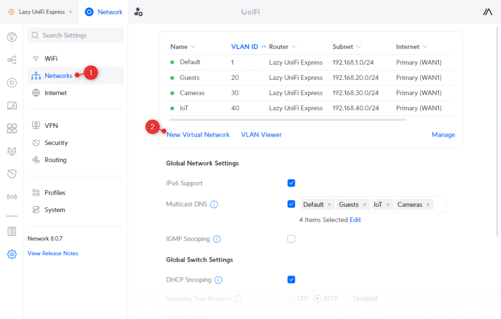
The first step is to create the different networks for the VLANs. I have used custom VLAN IDs in the steps below, but you can also leave Auto Scale Network on. This way UniFi will automatically create the IP Range and VLAN ID.
Open your UniFi network console and navigate to:
- Settings > Networks
- Click on New Virtual Network
We are first going to create the guest network:
- Enter Guests at the Network Name
- Deselect Auto-Scale Network
- Set the host address to 192.168.20.1
- Change Advanced Configuration to Manual
- Change the VLAN ID to 20 so it matches the IP range
- Enable Isolation by checking Network
- Change the Content Filtering to Family (optional)
- Click Apply Changes

Next, we need to create the network for the Cameras and IoT devices. Click again on New Virtual network , and repeat the steps below for both Cameras and IoT , using VLAN 30 for cameras and 40 for IoT:
- Network Name: IoT
- Disable Auto Scale Network
- Host Address: 192.168.40.1
- Advanced Configuration: Manual
- VLAN ID: 40
- Isolation: Off
- Click Apply Changes (and repeat for cameras)

Using VLAN Magic
If you are running UniFi Network 8.0.24 or higher, then you can also use the new VLAN Magic feature to create virtual networks. It allows you to create a new virtual network from the device overview, and simply assign devices to the VLAN by selecting them.
UniFi Network will then use the virtual network override feature to move the device to the assigned VLAN. The advantage of this method is that you don’t need to create wireless networks for your VLANs, but when applying this on a wired device, you will need to make sure that your ports are configured correctly (I will explain that later in the article).

To create a new VLAN with VLAN Magic:
- Open the Topology view
- Click on the plus icon the create a new VLAN
- Select the devices in the overview to assign them
- Click on Apply Changes
Step 2 – Block traffic between VLANs
With the networks and VLANs created, we need to block the traffic between them. By default, devices in, for example, the IoT VLAN, can access the device in your main VLAN. Guests however are already isolated by the automatically generated firewall rules by the Isolated Network option.
There are two options to block inter-VLAN traffic, we can create custom firewall rules, or use a Traffic Rule. The latter is a lot quicker to create, but I will explain both methods.
Note During my tests, it took a couple of minutes until a traffic rule was effective. So after creating a rule, give it a couple of minutes before you test it out.
Using Traffic Rules
Ubiquiti is really promoting the use of Traffic Rules to block or allow traffic on your network. It’s indeed a bit easier, but unfortunately, we can see the firewall rules that are created in the background.
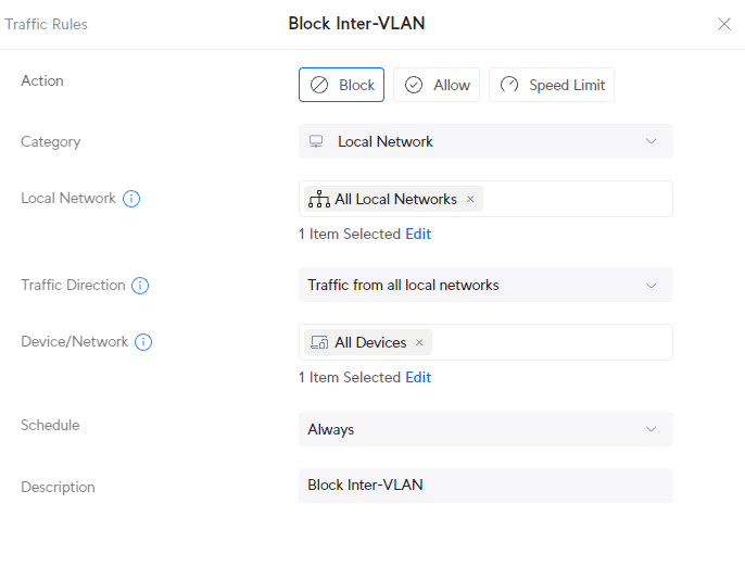
However, after some testing, we only need one Traffic Rule to block all Inter-VLAN traffic, which is a lot quicker than using firewall rules. Open Traffic Rules and click on Create Entry :
- Action: Block
- Category: Local Network
- Local Network: All Local Networks
- Traffic Direction: Traffic from all local networks
- Device/Network: All Devices
- Schedule: Always
- Description: Block Inter-VLAN
You probably want to access your IoT device, for example, from your main (default) VLAN. To do this we can create another Traffic Rule to allow traffic from the Default network to the IoT network. Now this is where Traffic Rules become a bit confusing for most, let’s first create the rule and I will then explain it a bit:
In the Traffic Rules click on Create Entry :
- Action: Allow
- Local Network: IoT
- Traffic Direction: Traffic to all local networks
- Device/Network: Default
- Description: Allow Default to Access IoT Devices
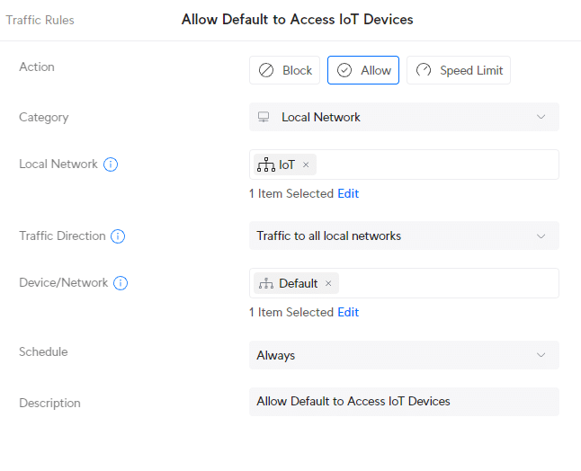
So what we have done here, is Allow all traffic from the Default network (Device/Network) to all local networks. And the local networks in this case are the select Local Network IoT.
I have only selected IoT here as local network, but you can also select the other VLANs you want to have access to from your default network.
Using Firewall Rules
We can also block the inter-VLAN traffic with custom firewall rules. This is however a bit more work compared to the Traffic Rules.
Before we can block the inter-VLAN traffic, we first need to create 3 other rules:
- Allow established and related connections
- Drop invalid state connections
- Allow the main VLAN to access all VLANs
Firewall rules are located in the settings under Firewall & Security:
- Click on Create New Rule

We are first going to create the rule that allows all established and related sessions.
- Type: LAN in
- Description : Allow established and related sessions
- Action: Accept
- Source Type: Port/IP Group
- IPv4 Address Group: Any
- Port Group: Any
- Destination Type: Port/IP Group
- Under Advanced: select Match State Established and Match State Related
- Apply Changes

The second rule that we are going to create is to drop all invalid states:
- Description : Drop invalid state
- Action: Drop
- Under Advanced: select Match State Invalid

And the third rule that we need to add is to allow traffic from our main VLAN to the other VLAN. This way we will be able to manage all the devices even if they are in IoT VLAN for example.
To create this rule we will first need to define an IP Group. Port/Ip Groups allow you to easily apply a rule to multiple port numbers or IP ranges. In this case, we want to match the IP ranges of all VLANs.
- In the settings menu, click on Profiles
- Scroll down and click Create New under IP Groups
- Profile name: All Private IPs
- Type: IPv4 Address/Subnet
- Address: 192.168.0.0/16 (this will match all addresses that start with 192.168.x.x)

With the IP group created, go back to Firewall & Security and create the following rule:
- Description : Allow main VLAN access to all VLAN
- Source Type: Network
- Network: Default
- Network Type: IPv4 Subnet
- IPv4 Address Group: All Private IPs (the IP Group that we just created

We can now create the rule that will block traffic between the VLANs. The rules that we just created will ensure that we can still access the devices in the other VLANs from the main VLAN. For this rule, we are also going to use the IP Group that we created earlier.
Click on Create New Rule in Firewall & Security and add the following rule:
- Description : Block VLAN to VLAN
- IPv4 Address Group: All Private IPs

We now have separated the VLANs in our UniFi network, preventing unwanted inter-VLAN traffic.
Step 3 – Block Access to Unifi Network Console from VLANs
Devices in your VLAN will need to have access to your network console (UDM Pro for example). But what we don’t want is that users (guests or IoT devices) are able to access the interface of our UniFi network console.
What we also want to prevent is that devices from IoT can access the gateway of the main VLAN.
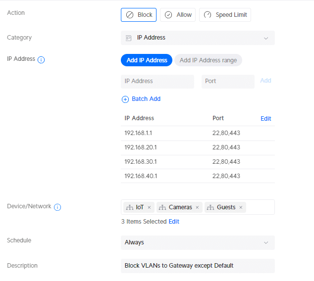
Now this is something that should be possible with a Traffic Rule in my opinion, but honestly, I can’t get it to work. I am still waiting for an answer about this from Ubiquiti. I created the following rule, if anybody knows why this isn’t working, please drop a comment below:
- Category: IP Address
- 192.168.1.1 – Port 22,80,443
- 192.168.20.1 – Port 22,80,443
- 192.168.30.1 – Port 22,80,443
- 192.168.40.1 – Port 22,80,443
- Device/Network: IoT, Cameras, Guests
- Description: Block VLANs to Gateway except Default
So for now, we will create a firewall rule for this. First, we need to create a couple of Port and IP Groups. Open the Profiles in the settings menu and click on Create New Group under Port and IP Groups . Create the following IP Groups:
The last Port Group that we need to create is to block only HTTP, HTTPS, and SSH access to the UniFi Network Console. The device will need to be able to access the gateway, but as mentioned, we don’t want to expose the console self.
- Profile Name: http,https,ssh
- Type: Port Group
- Port: 80, 443, 22

Next, we are going to add the firewall rules. This time we will be using the type LAN Local
- Type: LAN local
- Description : Block IoT to Gateways
- Network: IoT
- IPv4 Address Group: Block IoT to Gateways

And the rule to block access to the UDM Console. Note that we will be using the Port Group http,https,ssh here that we created earlier!
- Description : Block IoT to UDM Interface
- IPv4 Address Group: Block IoT Gateway Interface
- Port Group: http,https,ssh

Repeat the steps above but this time for the Cameras VLAN.
Assign devices to VLANs in UniFi Network
We have created all necessary rules to block inter-VLAN traffic, so all we need to do now is assign our devices to the correct VLAN in UniFi Network. For wired devices, we can assign a network to the port on the switch. And for the wireless devices, we will need to create a separate SSID.
Assign VLAN to Switch Port
By default, each switch port allows all tagged VLAN traffic. This means that if the connected device has the correct VLAN ID configured, it can access that VLAN. Which for most situations. It also allows access points or switches to pass through traffic from all VLANs if needed.
But when we have a network camera or smart home device connected to a switch, then we want to only allow access to the corresponding VLAN. The device should not be able to access any other VLAN (by changing its VLAN ID for example).
To do this, we will need to configure the Native VLAN on the port and block all tagged VLAN traffic.
In the UniFi Network console , open the new Port Manager and select your Switch . We are going to use the new Ports Manager because this will give you a create overview of all your switch ports and VLANs.
Tip By default, you can select and change multiple ports by just selecting them one after another. Mind this when you want to change another port.
- Open the Port Manager
- Select the Switch
- Select a port of a camera or smart home device
- Change the Native VLAN to the correct Network (VLAN)
- Change Tagged VLAN Management to Block All
- Reboot your Camera by Power Cycle the port

Change the other ports as well, assign them to the main VLAN by selecting the Port Profile LAN or another appropriate Port Profile.
Make sure that you Allow All Tagged VLAN traffic on the Uplink port (recognized by the up arrow ^) and the access points port
Assign VLAN to Wireless Devices
If you have a UniFi doorbell, for example, you might also want to assign this device to the camera’s VLAN. The problem is that we can’t set a VLAN on the doorbell itself. The same problem occurs with a lot of IoT devices, on most, you can’t configure a VLAN ID.
So the only option is to create a separate SSID (wireless network) for each VLAN and assign the wireless network to the correct VLAN.
Note We can also use Private Pre-Shared keys for this. This way you only have one SSID, but depening on the used password, a device is assigned to a different virtual network (VLAN). But I have noticed, that not all devices seem to work well with this yet, so make sure you test it out properly.
- Open Settings and select WiFi
- Click on Create New WiFi network
- Enter a name and password for the wireless network
- Change network to the correct VLAN (IoT for example)
- Click Add WiFi network

You can change the WiFi connection of your UniFi Doorbell in the Protect Console > Devices > Settings > WiFi Connection.
Creating Firewall Exceptions
Sometimes you need to allow access between specific devices in different VLANs. In these cases, there are again two options to allow this. We can create a Traffic Rule or add a Firewall rule.
Using a Traffic Rule
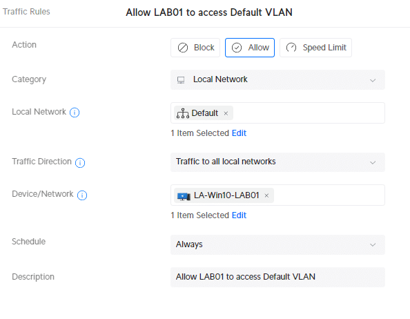
Traffic Rules are the most convenient to use for this. We can simply create a new rule where we can select the device that we want to give access to the specified VLAN. For example, to give the LAB01 notebook access to the Default VLAN, we can create the following traffic rule:
- Local Network: Default
- Device/Network: <select-device>
Using a Firewall Rule
When using a Firewall rule, we need to create an allow rule and place the rule above the Block VLAN to VLAN rule. Let’s take the following example, allowing IoT devices to access a Raspberry PI in the main VLAN.
When you create an allow rule, try to be as specific as possible. If it’s only between two devices, then use the IP Address of both devices. If you know the protocol, then specify the port number as well.
Create a new firewall rule:
- Type: LAN In
- Description : IoT to Raspberry Pi
- Destination Type: IP Address
- IPv4 Address: 192.168.1.x

Next, we will need to move the rule above the Block VLAN to VLAN rule that we have created in the beginning. You can drag and drop rules using the 6 dots at the beginning of the rule:
- In the Firewall Rules select LAN
- Drag the new rule above the Block VLAN to VLAN (Rule index 2003)

Wrapping Up
VLANs allow you to secure your local network by making sure that devices from one VLAN can’t access the other. Because inter-VLAN access is by default allowed in UniFi, we will need to create quite an amount of rules before we can safely use it.
I hope this article helped you to set up UniFi Vlans. If you have any questions, just drop a comment below.

Hey! I'm Ruud. I work as an IT Consultant in the Netherlands and love to write about IT, Microsoft 365, PowerShell and Smart Home stuff.
You may also like the following articles

UniFi G5 Turret Ultra Review
UniFi Protect 3.0.x Update

How to setup UniFi Dynamic DNS (DDNS)
174 thoughts on “how to setup and secure unifi vlan”.
Hi. Great Article, thanks.
Followed you Article on an Installation with Unifi Cameras. Created the VLANs and Rules exactly like in your Article. But as soon as I change the Native VLAN from the Default to my Camera VLAN DHCP stops working on that Port. Also my Camera VLAN WLAN cant give out DHCP Addresses. Any Idea why that happens?
Have you enabled DHCP for the Camera network?
Good afternoon Rudy ,
In your section Assign VLAN to Wireless Devices, you are explaining that If you have a UniFi doorbell, for example, you might also want to assign this device to the camera’s VLAN. The problem is that we can’t set a VLAN on the doorbell itself. The same problem occurs with a lot of IoT devices, on most, you can’t configure a VLAN ID.
My question was why not just assign these devices to the IOT network ? That way the device would connect to the right VLAN no? For example if i set my doorbel to the Camera IP of 192.168.30.1, It would pulled an IP address from that therefore be assigned to VLAN 30. At least i think it would.
If you go to device in your UniFi network console, you can select the device > settings and then under IP Settings use the virtual network override option. This way you can assign a device to a specific virtual network.
First off, I just want to show my appreciation and thank you for such a well written and comprehensive how-to article. I was confused about VLANs and using this article I was able to get everything setup. I followed ALL instructions and created the necessary VLAN and WiFi networks, and Traffice Rules when possible over Firewall rules. I did everything except for Step 3 “Block Access to Unifi Network Console from VLANs”. Has this issue with the traffic rule been resolved? If not, as with other commenters, I’m still confused why this is an issue. If an IoT device manages to get access to the default network gateway address of 192.168.1.1, I have a VERY strong password setup (24 characters long) and have 2FA setup, so rally what is the danger? My apologies but I’m still confused about this. Thanks !
There is indeed not a real danger from a IoT device. But in larger environments with guest networks for example, you just want to compeletly shield of the gateway. Security is all about adding layers, a strong password is one, seperating networks is another, and restricting access to a device is another.
Compare with securing an warehouse. You have a good lock on the door, so they won’t be able to enter the warehouse. But by placing a fence around the warehouse, they won’t even be able to access that door, so they can’t even try to open the lock.
Great article, thank you!
I had a comment/question about the “Assign VLAN to Wireless Devices” section.
You state: “So the only option is to create a separate SSID (wireless network) for each VLAN and assign the wireless network to the correct VLAN.”
It looks like if you go to Clients > > Settings there is an option for “Virtual Network Override” which seems to allow you to assign a VLAN to the client. Would this not be a valid alternative to having to create a separate SSID for each VLAN?
Yes, virtual network override can be used as well. Is has only be available since the last couple of months, and it’s not working with every device or console.
I’ve used this article recently to configure a small office, and it’s great. Thanks for the writeup! I have everything working smoothly, but one thing is still nagging me.
Your first step is to create a Traffic Rule to prevent Cross-VLAN traffic, which I did, and it works perfectly.
I have three VLAN’s – one secure, one for less-secure devices, and one Guest all on 3 different Networks, and 3 SSIDs. If I checked “network isolation” on Less-Secure and Guest hotspot, do I even need that traffic rule? Or would the secure VLAN still have cross traffic because you can’t check network isolation on your Default network?
And then to add onto that, should I even bother checking Network Isolation on those two? Does that rule take care of that?
Network isolation isolates the clients from each other on the same network. So yes, you should enable it on the guest network atleast. Guest isolation alone should work as well, but with VLANs you can also set differenent access restrictions on the network, like bandwidth limiting.
I think it’s “Device Isolation” that isolates clients from each other on the same network, “Network Isolation” is for cross VLAN traffic:
From Unifi: “Device Isolation blocks traffic between devices on the same Virtual Network (VLAN) whereas Network Isolation blocks IPv4 traffic between VLANs.”
So i’m assuming your Traffic Rule (block cross VLAN traffic) makes checking Network Isolation redundant? Your rule works great, so i’m assuming it’s not necessary. But Unifi does recommend using Network Isolation (vs Traffic/Firewall) if you are also using a Unifi Switch in conjunction with a Gateway.
No, in case of a guest network, you often want to isolate the guest devices from each other as well.
Never Mind, I got it to working with my allow airplay rule, and correct port numbers. it sometimes takes some minutes for unifi to understand new firewall rules.
Hello great instructions, but airplay is not working if I have my airplay devices on IOT network, is there any way to fix this, i also have mDNS on
Excellent article, many thanks. See, I was afraid of locking myself out of my router but you explained it nicely and showed how to prevent that from the very first rules.
I have a question around how to prevent anyone or anything self-assigning an IP in the default network. As the UDM resides on 192.168.1.1 I have vacated this subnet as much as possible but also run pi-hole and couple other components. I have turned off DHCP and limited the subnet to a /28 but I have a few gaps in that range. How do I block those IP’s from being used, say if I manually set my IP on a laptop – how to stop it from communicating on the network? There is no MAC address filtering on a network, that only exists in WiFi. Would I need to implement 802.1x, use traffic or firewall rules to effectively null the IP’s in 192.168.1.0/24?
I hope I am explaining this correctly.
Thank you for your time. Bruce
That is quite difficult to accomplish. I would create some Traffic rules for does specific IP addresses if it are a few.
Hi Rudy! Great guide. It brings a lot of new insights 🙂 One thing though: I’m confused as to why (part of) step 3 is necessary. When you already block VLAN to VLAN communication, doesn’t that include the .1 addresses of the other VLANs? (The block access to the console is clear to me). If that’s true, you’d only need to block HTTP(S) and SSL access to the gateway of its own VLAN.
Am I missing something here? Your solution seems (too) redundant.
Because the other subnets are also available on the same interface on the gateway. So we will need to block all IP addresses.
Great post, helped me a lote with my UDR. Any luck blocking Teleport VPN traffic from accesing the console admin or the main VLAN?
That is not possible at the moment. Is a known issue unfortunately.
Thanks for the very detailed HowTo’s, it helped me a lot improving overall security of my home network.
May I ask you your help (more an explanation actually…) on how I can achieve the following:
I kind of have the network layout setup according to you layout.
My default network is 192.168.2.0/24 and on the UDM-pro there are some more VLAN’s which are not relevant for my issue. I’ve setup a L2TP siste-to-site VPN server (192.168.60.0/24) to let some remote Synology NAS systems “call home”.
The clients are able to connect but it basically stops there. The remote clients are able to ping to the UDM-pro. The UDM-pro is also able to ping to the remote client and I can SSH into them, that part is fine.
However, when I try to ping from my default network (a W11 client in the 192.168.2.0/24 network) to the remote client (192.168.60.x) the requests will time out, the same happens in the other direction.
Can you point me in the right direction on how to resolve this?
Thanks in advance!
Most likely you drop all traffic coming from 192.168.60.x. Make sure that established connections are allowed.
Meanwhile I discovered that L2TP has it’s limitions on pushing routes. To make life easier I switched to the built-in OpenVPN server which pushes most part of the routes to the clients. To add missing routes you need to make some changes in the .ovpn file you can download and add them in the client config file.
Works like a charm now 🙂
To use the downloaded client configs where a Synology NAS is the client you have to remove these 3 lines:
# Downgrade privileges after initialization (non-Windows only) user nobody group nogroup
For a little more safety, change this line:
cipher AES-256-CBC
cipher AES-256-GCM
If you want a full tunnel add this in the client before the certificate part starts:
redirect-gateway def1
If you want split-tunneling don’t add that line.
If you need additional routes which aren’t pushed by the OpenVPN server running on the UDM add one or more of these lines (adapt to your needs):
route 192.168.x.0 255.255.255.0
Hi Rudy, Thanks for writing the article it’s helped a lot, but….. I don’t have a UDM, my system is based on a USG 3P and a UCK G2 Plus with a few Unifi switches and AP’s. I’m trying to connect my neighbor to my Broadband connection (he hasn’t any) using a couple of Loco M5’s in Station/AP bridge modes – that was the easy part to set up….. If I just connect the Station M5 it to my network LAN, he can see all my devices and I can see his – not a good idea!
So I’m trying to implement a separate VLAN to connect the M5 bridge to.
I’ve followed your steps and have succeeded up to a point.
If I isolate (tick the Isolation box) for his VLAN10 (192.168.10.xx) all works fine, except he can ping the USG at 192.168.10.1 – but can’t login as he hasn’t the password. So that’s OK, but as I’m on the default VLAN1 (192.168.1.xx) I can’t access the M5’s to change any settings.
So I need to implement your Step 3 – Block Access to Unifi Network Console from VLANs etc…..
But you’ve lost me I’m afraid.
Originally my Network OS was v7.xx but have upgraded to UniFi OS Version 3.2.10 which included Network OS v8.0.28. – quite an upgrade… I eventually found Traffic Rules in Security>Firewall Rules>Create Entry. but it’s not available, using the link just gives ‘UniFi is having trouble with this direction’
So I need more help with doing it using Firewall Rules please.
Thanks, Colin
Traffic rules are not supported on the USG. You will need a next-generation firewall.
Brilliant articles on UDM. It’s beneficial and up-to-date!
Thanks so much. The Traffic Rule block bug still exists for Gateways 🙂
What would i need to block if i just want to block wifi on a different vlan from accessing the main network and access to the dream machine? Thx
You would need to create a separate network for that. You can’t just block all clients connected through the WiFi.
Traffic Rules are created in the LAN-IN chain and take precedence over the LAN-IN Firewall Rules. Blocking to the Gateway IP’s requires LAN-Local rules.
I suspect this is done to prevent people locking themselves out of their controllers.
Very help-full article, thanks a lot!
How to block communication between clients in a specific VLAN?
Between all clients or between specific clients? For the first you could use network isolation and for the second you will need to make sure that the clients have a fixed IP Address. Then you can make a traffic rule for it.
I do not have access from my main vlan to devices in other vlans. I paused all rules.
Does anybody know why that is so?
Did you create the traffic rule to allow access from your main VLAN? (Allow Default to Access IoT Devices)
I am having a similar problem – I have paused the firewall rules and have created the traffic rule to allow access as stated above. Any ideas?
Thank you for this tutorial and relatively up to date screenshots (Unifi keeps tweaking) to help me with my UDR.
I followed everything you did and it works beautifully! Now when I went to allow my IoT network to my Plex sever hosted on Default I ran into issues.
I tried the Firewall Rules and placed it at the top. Tried a few different iterations of this but none of them would work. I finally tried your Traffic Rules method pointed to an IP address of my server with the port and it finally worked.
Action: Allow Category: IP Address IP Address: Device/Network: IoT Schedule: Always
I used Traffic Rules to create the blocking of VLAN traffic. So I can only think that the Traffic Rules were not playing well with the Firewall Rules for allowing certain traffic through. Thought on what I did (outlined above) and thoughts of why it may not have worked with Firewall Rules?
We can see the firewall rules created by the traffic rules, so you can’t place your firewall rule above the rule created by the traffic rule. That’s why it’s probably not working.
Your traffic rule looks fine.
Thanks for the input! It’s chugging along and got my toes submerged into it.
Hello, I used your settings for VLAN blocking. However, I need advice on one thing. I have 2 houses (different VLANs) with cameras in both. Let’s say house 1, where the NVR is located, has the IP 10.30.0.1, and house 2, where the other cameras are (connected wirelessly via AP), has the IP 10.40.0.1. In house 2, VLAN 10.30.0.1 is set on the port for cameras, but the NVR in house 1 cannot see the cameras. I’m interested in how to set up a rule or firewall so that the NVR can see those cameras.
Create a seperate VLAN for the cameras and NVR, and use that in both houses. Or alternatively, create a separate VLAN for the cameras in house 2, and use a traffic rule to allow access to and from that network to the NVR
Great article! I am new to UniFi equipment and have a question about your article. Is there a way to setup a secure/isolated network for port forwarding for hosting a game server? It looks like the guest network setup may work, but I want to make sure I have any additional steps needed. Thans for any help! Happy New Year and Best Regards, Tony
Guest network could be an option, but you can also create a new VLAN for it while making sure that you created the inter-VLAN blocking rules.
Will the traffic rules allow me to access my printer on IoT network? Right now I’m not able to an upon searching lots of people have the same issue with HP printers.
If you create the allow rule for the printer, then yes it should work.
Can I ask a vlan question regarding guest networks?
Using the 8.0 unifi console I had originally created a vlan with the “isolation” option checked and then a wifi SSID as “open” with the “hotspot” option checked. This worked but required my “guests” to login to the hotspot portal to access the network. I decided I preferred an easier approach so that guests could scan a QR code to connect to the guest network.
I left the vlan with the isolation option set but change the SSID to wpa2/wpa3 and unchecked the “hotspot” option. I then created a QR code for the SSID and all works fine. But, guests then had access to my main vlan.
Lastly, I create a couple of firewall rules. 1 to drop traffic from guest->main and 1 to drop traffic from guest->iot. This seems to work in my testing but wanted to see if I am missing anything that would cause a security leak.
Any thoughts?
You will indeed need to use firewall rules or traffic rule to block inter-VLAN traffic. I just updated the article with the required Traffic Rules for this.
Thank you for the write up. It is really helpful. Unifi now tells me to user Traffic Rules instead of the firewall rules. They seem to be easy to setup. Do you think they are better and easier than the firewall setup?
Traffic rules can problably also used, but it is basically another way to great the same rules.
Hi, Rudy. On the part “Step 3 – Block Access to Unifi Network Console from VLANs”. Are there any easier ways of doing this with 10+ VLANs? I mean … Instead of two rules for each VLAN, could it be done with a more generic rule that allowed VLAN 1 to access the UDM, but everything else for everyone else is closed? Of course they would need DHCP-respons and stuff, but DNS shouldn’t be needed (I use Quad9 and so on), and definetily not https/http/ssh from any other VLAN than default. I am going to build a dormitory network with a UAP-AC-IW in each room, with it’s own VLAN on the WLAN and outgoing ports. Each room should only need itself and Internet. No need to reach anything else. It would be quite time consuming and possible forgotten if I need to rules for each VLAN created.
I haven’t found a solution yet. I though Traffic Rules would be a solution for this, but that doesn’t seem to work when it comes to blocking http(s) and ssh access to the gateway.
Thanks for the detailed write up.
I was able to get the “block UDM gateway” as a Traffic Rule by specifying the IPs using CIDR notation like this:
192.168.1.1/32:22,80,443 192.168.20.1/32:22,80,443 192.168.30.1/32:22,80,443 192.168.40.1/32:22,80,443
I think this is a good case to change the default port for access to the gateway when an http(s) ui is enabled. It would seem to me that if you block traffic on common ports per IP (80,443) you may also block services running across that port, not just access to the console itself.
In step: Assign Port Profiles to Switch Ports, it seems the Unifi menu options have changed. The Port Insights page has changed. Should we be changing the Ports Page’s Native VLAN/Network to “Cameras”per your example and have Tagged VLAN Management set as Allow All?
I have updated the article
Just wanted to share my thanks for this write-up, was easy to follow and helped me clean up a few of my newbie-mistakes in my home setup.
I cant get Printer access to work. I have my Printer on VLAN 20 my IOT VLAN I set my IP to 10.0.20.80. Im not able to ping this IP from default. I used your rule IOT to Raspberry changing it to default to 10.0.20.80. I still can not ping my HP Printer. Any help is greatly appreciated. Ive noticed a lot of people have issue with printers.
Hi, as far as I know I followed the tutorial to the letter. I have an issue with DHCP. For example my IOT network is defined to be in the range 192.168.40.6 – 254 by the DHCP settings for that network. However, when I connecf a client (like a windows pc f.i.) it does NOT get an IP address assigned. My DHCP settings are :
DHCP mode: DHCP Server DHCP Range: 192.168.40.6 – 192.168.40.254 DHCP default gateway : tries both 192.168.40.1 as well as Auto
What could possibly be wrong and what should I verify ?
Big thanks !!!!
is the PC connected to an access port on a switch set to that same vlan? are the vlans from the unifi console trunked to the switch you are connecting it to?
Hi this realy helped me. Thank you for your hard work.
Great guide, thank you !
Question … When a IOT device sits in a specific Wifi network, assigned a VLAN ID … I see it connects to the network without issues, however the IP address of that device does not show in the Unifi Client list interface ?
Great guide , much appreciated .
Can you pls expand your guide with the steps required to route VLAN traffic through the new UniFi magic VPN. I’ve 2 sites connected via Magic VPN with Cameras on each site but one NVR in a single site only. I want to use one VLAN for all the cameras and their NVR so would this be possible with the new UniFi magic VPN as it’s very easy to setup?
I would imagine that would be policy routing approach and work around for traffic in 2 layers 2 and 3 (based on my limited understanding) , will this be possible? What are the steps to implement it?
thanks for this nice guide. Finally a guide which describes all settings on the new unifi ui.
Why is it necessary to add the Rule “Block IoT to Gateways”? Why should the IOT devices be blocked from reaching its DHCP or DNS Server?
When I add the rule I’m not able to add new tuya devices.
It should be able to access the DNS and DHCP at it’s own gateway address 192.168.40.1. We only block http, https and ssh there.
Ruud, thank you, this is an excellent article!
I don’t quiet understand two things, only concerning the “Block traffic between VLANS”: – Allow established and related connections – Drop invalid state connections – Allow the main VLAN to access all VLANs – Block VLAN to VLAN
1. For the first two rules you use as source “Any” and destination “Any”. For the fourth rule you use as source “All Private IPs” and destination “All Private IPs”. I get the logic for the fourth rule but don’t understand why the first two rules are “Any”. Wouldn’t it be enough to just use “All Private IPs” as well?
2. I do technically understand what the second rule does “Drop invalid state connections” but I don’t understand why it’s used here? Is that just a best practice thing to do?
The first question is for understanding but the second one is if particular interest to me as I see some traffic being dropped and not sure this is right, e.g. I have Apple devices in my network and they seem to want to contact Couldflare (1.1.1.1 and 1.0.0.1) and those connections are being dropped now as invalid.
Appreciate any comments. Cheers!
1. These rules also apply to connection to the internet 2. The firewall not only blocks strange or messed-up packets but also rejects any packets that don’t belong to an ongoing conversation. Think of it like this: if you were getting a file, and the transfer finished, the connection would close. So, if the server sends more data after that, the firewall sees it as odd because there’s no active talk going on. To be safe, it’s smart to have these rules to stop any weird attempts from a compromised device.
Perfect and simple example of vlan’s setting up. I doubt about iot and video restriction access to router, this case you can’t control smart homing and NVR remotely, but it can be tuned individually. What you can advice for such trlcky task: secondary wan link (ethernet) present near usw24 (not L2) switch, connection to UDM Pro via optic. There are free ethernet ports at usw24 and at udm-pro. Is it possible to build isolated trunk between ethernet ports to path trough this wan link to udm?
hello, what about trunking? what would be the configuration for having all created vlans including the management vlan trunked out of the UDM on a single port, down range to other switches trunk ports to expand my network?
You can use the port profile all for that.
After setting up VLANs and triple checking firewall rules, I have a couple of devices in my IoT network that can only be accessed remotely or from the IoT local wifi network. Shouldn’t I be able to access them from the default local wifi network, too? Feels like I missed something.
Thanks for a great article…very helpful.
First, thank you so much for the guide.
I was wondering if you could explain a bit more on why you have LAN In for some, and LAN Local for others?
LAN In rules applies to traffic the enters the LAN from the internet. LAN Local applies to traffic that comes from within your local network.
`LAN In` is from internet? Wouldn’t that be `WAN In`? Cause all the rules in this article are `LAN …` for blocking inter VLAN traffic — nothing about internet. I’m a bit confused?
The labels are indeed confusing: LAN-IN = traffic entering the LAN interface (usually sourced from clients on the LAN, but VPN traffic is also filtered here). Also traffic from the WAN interface to the LAN interface can be filtered here. LAN-OUT = traffic leaving the LAN interface (destined for the LAN clients) WAN-IN= traffic entering the WAN interface (usually sourced from anything on the internet) WAN-OUT= traffic leaving the WAN interface
I researched some more and I think I figured it out.
Conceptually, `LAN Local` is the same as `LAN In` where `destination` is the UDM itself.
But, if traffic comes in where `destination` is the UDM itself, the UDM does not trigger `LAN In` rules. Hence why those rules need `LAN Local`.
Now I get it. Thank you!
First, thanks for the article, it’s been very helpful!
Correct me if I’m wrong, but I believe the “Block VLAN to VLAN” rule you created at or near the beginning makes blocking access to the group of gateway IP’s that are in your other VLAN’s unnecessary, as they should already be blocked, right? Thus, I think the only rule needed would be the one to block http,https,ssh to the gateway interface for said VLAN.
That is what I thought too but Unifi does not trigger the `LAN In` rules for traffic destined to the router itself. Thats why you need the other `LAN Local` rules.
Hello, I wanted to ask. If port 443 and HTTP, and HTTPS are blocked, how do you connect to the unify web interface control window? Do I need to connect directly through the computer after downloading the unifi program?
Have you installed the controller on a Windows computer? Port forwarding or a firewall execption is the best option
I am a mac os user. I haven’t installed anything on my computer yet. That’s all it takes to install the controller on the computer and I’ll be able to connect? maybe you have written somewhere in your blog about creating firewall execption rules to connect to UDM?
443 is only blocked from IoT. So devices on your main/default can still access the Unifi web interface control from your LAN.
I am thinking of upgrading the home network to something more serious. I am choosing between meraki and unifi. Do you think unifi has a good enough firewall like cisco? and I wonder if cloud key2 can be connected to cisco meraki router.? if I would like to add wifi cameras.
Thank you for you opinion
I prefer UniFi. It’s easier to set up and you don’t need monthly licenses to run and configure your hardware. The firewall of UniFi is good enough for a home or small business network. You can place the cloud key behind the Meraki router.
Thank you for your reply. I’m thinking about UDM/SE, although at the moment the internet provider only offers 1GB internet speed. Maybe in a few years there will be a higher speed. Investment in the future. I’m also thinking about acces point pro, it should probably be enough for an 88 sq m apartment.
Hey Ruud, I wanted first to say that your article was very helpful and thank you! With that, I’ve found two oddities that perhaps you could provide insight into. First, when I run an external scan of my domain (strictly housed behind the UDMP running Network 7.4.150), I find that I have a ton of ports open. I’ve confirmed that I have UPnP off, so no ports are being opened for arbitrary services. I can’t figure out why they are open.
The second is regarding securing IPv6. I’d like the same VLan structure in place, along with the firewall rules to match that coincide with the IPv4 rules and VLan’s. I currently have about 40-50 devices of various types and am trying to slowly transition to IPv6. Do you have any ideas on how to approach this, or any good references that could point me in the right direction?
And you have threat management running? I don’t have any experience with IPv6 and vLANs yet.
Oh wow, perfect article to guide a beginner like me. Many, many thanks. After setting up the groups to block port 22,80,443, I can no longer SSH to a machine on the blocked network. For now, I have excluded port 22 but would rather add a rule to allow SSH from the blocked VLAN to a specific machine on my main network. Any examples?
Thank you for year great tutorial! I have tried to implement a similar setup using USG-PRO4 and UniFi Console 7.4.150, but did find that Switch port profile configuration under which you referred to as “new Ports Insights feature” was not available. There are some other differences as well. Do you know if I should be able to set up a similar solution without a UDM? If not would you be able able to point out what I need to configure different? Thank you in advance
Great article Rudy – thankyou. I guess like many who found this article I was perplexed by the “problem” that inter-VLAN traffic is allowed by default, having set up VLANs which did “nothing”. This article has saved me hours. The rules Unifi creates with the same description are indeed “Internet In”, “Internet Local”, or “…v6…” rules and cannot be edited and the detail cannot be viewed, but I could take a reasonable guess at what they do. I read a post from Unifi that suggests they cannot be edited/viewed to “…enable the best user experience” – saving us from ourselves perhaps. UDM 7.3.83, U6-LR, u6-Lite, USW-Lite-8-poe.
I followed this tutorial and everything seems to have worked – perhaps too well. I cannot access my HDHomerun Flex 4K tuners from a different VLAN. Everything I’ve read online seems to suggest a tricky situation working with HDHR devices and VLANs. Wondering if there’s a simple way for a non-IT weekend warrior like myself.
What I hope to accomplish is to regain access from my Pixel 6 (VLAN 20) to several HDHR devices (VLAN 1). Is there a firewall rule to use? I’ve tinkered without success so far. Alternately, should I consider moving the HDHR devices to a separate VLAN? Might that clear things up? I have an unused MEDIA VLAN in my network list; no devices are assigned to it yet.
Ideally, I’d like all mobile devices on VLAN 20 to have access, so if this involves a new profile/group then I’d like help with that as well.
Thanks, Robert
Would any of these rules stop internet in traffic? I set up the vlan for having a game server separated from the rest of my network but the port forwarding is still blocked after creating a rule. I can get OUT from the vlan but I can’t get in.
When configured wrong it can stop internet traffic indeed.
First off, I love this site as well as the simplicity of the information you presented on this topic. I was able to follow along on this tutorial and get firewall rules set up properly. Now my IOT network is isolated from all others on my UniFi Dream Machine Pro. Thank you! This tutorial was much easier to follow than the dozens of YouTube videos out there claiming to “make it easy”. I’m not an IT professional so all of this is sort of “weekend warrior IT” for me.
A question I have on the HTTP, HTTPS and SSH group profile. I use ports 80 and 443 to renew SSL certificates every 90 days. I have port forwarding for 80 & 443 disabled until I need to use them. Should I expect that group profile to interfere with those certificate renewals? Is disabling the profile sufficient while renewing, or can I remove ports 80 and 443 from the profile?
Thanks again! Robert
Disabling the profile (or switching the port to another profile) might be the easiest option.
I think I got the tutorial right, but from the beginning my vlan doesn’t seem to assign an ip. I have just one pc plugged into a port on the switch that is set to use this vlan (called “gaming” in my case) but it gets no ip when then pc is plugged in.
Is DHCP enabled in the vlan? If you go to network > select your gaming network, scroll down to advanced > DHCP
Thanks, got it figured out, it was my own stupidity 🙂
Hi all, thanks for useful post and comments! I have from Ubiquiti only a USW PRO 48 POE switch and the CloudKeyGen2Console. I have set the vlans (100,200,300) across the router and switch (only 1 router only 1 switch), but trying to get the printer on vlan 100 to be accessible from 200 and 300. how do I do that? tried different option but not successful so far and see in this post some functionalities are not available to me… thanks for any suggestion/feedback!
The cloudkey alone isn’t sufficient for this. You will need a router or this as well.
Can you set the printer so it’s not on a vlan and allow traffic from all three vlans to access the port the printer is on?
Thanks for the guide, I’ve gotten to blocking the UDM interface and I don’t have the option in the red box. Am I missing something or did they update the interface?
Are you sure that you have selected Destination Type : Port/Ip Group?
Ok, I followed this to the letter and verified 3 times that I made no mistakes but I can’t get any trafic between VLAN’s. I have a camera server on 192.168.1.1 (Default network) that can’t a ping a Camera that had it’s ip set via DHCP on VLAN id 30 192.168.30.217. I brought back this cam on Default LAN and I had no issue to ping it. Is there an easy way to see what firewall rules block this traffic ? (running 2.4.27)
No, unfortunately, we can’t see the firewall logs easily.
Drat, new UDM Pro, updated to version 2.4.27, a lot of this stuff looks different. I am at the step: “Next, we are going to add the firewall rules. This time we will be using the type LAN Local”, however, LAN Local is no longer an option.
The Firewall & Security Type pulldown has: Internet In, Internet Out, Internet Local, and LAN in.
Any idea which of those updated pulldown choices are equivalent to “LAN Local”?
You can scroll through the dropdown (it isn’t very clear sometimes that you can scroll)
Ok im back and have sorted out my cable issue. I thought this was resolved because I could print from my phone. I was thinking ok things are talking. I have now realized that my phone was the only device that could print. I have the firewall rule established and related but that doesnt seem to work. I also can not ping the printer. I have it wired to a static IP.
Hello Rudy, Thanks for the step by step tutorial on setting up the UDM PRO it is invaluable in understanding VLANs. It was hard finding information on how to setup VLANs on the UDM PRO until I came accross your article. However I have a consistent problem between three of these Dream Machines (UDM PRO). I followed your tutorial almost to a T on a out of the box new UDM PRO. When done with the configurations, I am not able to set the LAN ports on the UDM PRO to a specific defined network. The only option is “ALL” or “Disable” with “Default” and “Networks” grayed out under a port profile. There must be something basic in the setup that I am missing. Can you help?
Just to be sure, you can normally scroll down. Default and Networks are “headers” in the dropdown list (and indeed greyed out). So under Default, you will see All and Disable. And under Networks, you will find the network profiles that you have created (after you scrolled down).
Hello Rudy,
I spent hours trying to setup VLANs with multiple Dream machines, unlike other pull downs in the dream machine settings the one for configuring switch ports on a specific VLAN this pull down has a hard to see side scroll. Not too straight forward in my opinion. Thanks for your help
Would it be possible to achieve the same setup using the Traffic Management option (local network category)?
Good morning Ruud, Do I really need a UniFi Security Gateway or UniFi Dream Machine (UDM, UDM Pro) for creating different VLANs on my network? I hava a nighthawk R7000 router to which I attached a 16PoE lite and I have a 8 PoE lite connected to the 16 PoE switch. To the 16 Poe I connected 2 Unifi AP’s, Hue bridge and solar pannels. Doorbell, chromecast and google home mini are connected via wifi. To the 8PoE switch I connected 1 unifi AP and a desktop. Kind regards
Well, it makes it a lot easier. You can also create the VLANs on your router, and then create the appropriate wireless networks in the UniFi Controller. That should also work.
hello rudy thanks so much for this tutorial, finally beginning to understand things a little bit. followed everything step by step including firewall rules and so on everything works perfectly as far as i can see from within the wired network. the main vlan has access to all other vlans and all other vlans cannot reach the main lan and each other. so far so good. however only from the wifi assigned to the main lan i cannot access the other vlans , which should be possible ( allow main network to all vlans — source main network destination all local ip adresses ) deleted the wifi networks reinstalled them , checked the groups on faults etc etc . this drives me a little bit crazy it is probably something small but i have no idea whatsoever may be you or somebody out there can give me a hint in the correct direction thanks dank je wel paul
Do you have any write ups on creating a mgmt VLAN for access points? I don’t want my APs to use the default VLAN since we already have an AP mgmt VLAN in place. Applies to the unifi controller software on a server.
Hi, thanks for this great tutorial !
Just one thing .. when creating the networks, I have the option to select the “Network Group” … (assigned to a specific port on f.i. my USG) .. I select LAN2 Here ? (This is the 3rd port besides WAN and LAN1)
Thank You !!!!
Yes that should work
Hi, Excellent write up. Thanks. I’ve got just one question. In my main vlan (default) i have a machine which runs an application (on for example port 4333). How can i configure devices from the IoT vlan to connect the machine in the main vlan (default) by only this port?
I red you’re exceptions and tried a port group with port 4333 to the particular machine’s IP). But wasn’t succesful.
Exceptions can sometimes be a bit of a trial and error. Make sure that you order the rules correctly. And you can try to allow access first based on IP and if that works narrow it down to specific port only.
i have an UDM and have aproblem with wifi and wlan. i created a network (IOT-Devices) and enabled DHCP servicer in this network. as well i assigned a new SSID in wifi and added this to the network. I can connect with a client to this network but i won’t get an DHCP Ip address to my device. is there an additional setting to get DHCP to work
this is exactly my problem
I also have this problem. No matter if I create a Guest network or a IoT network i cant get a ip from the dhcp in that network. Have anyone found a solution for this?
Same here…. looking in other forums to see if I can find the issue.
Same here. Any solutions anywhere?
Seeing this also. Any luck? Rudy?
Just did a quick test here, and seems to work fine. But I see that I haven’t mentioned the DHCP server settings in the article. Can you please check the following:
– Open Settings > Networks – Select the IoT network – Scroll down to Advanced Configuration – Check if DHCP mode is set to DHCP Server – And the DHCP Rnage is in the same subnet as the IoT network is 192.168.40.x – 192.168.40.200 for example.
Confirmed that DHCP Server is there along with the subnet range it needs to be in.
To me it almost seems like firewall is blocking it. Do we need to let the DHCP server traffic through on UDP ports 67, 68? I would think that each network would handle its own DHCP but that doesn’t seem to be the case.
Getting no router IP and 169 address when connecting (hangs trying to connect on devices essentially)
No that should not be necessary. How is the client connected? Directly to the UDM Pro?
So it’s a UDM connected to a switch and then I have a few devices connected to that including a couple UI wifi 6 aps.
I think my issue might be the switch actually and it not handling vlan traffic. It’s a Ruckus switch and therefore I don’t think it understands the vlan traffic tagged.
That could indeed be a problem. Also, make sure that you have set the port profile to all for the connection from the UDM to the switch.
Just a heads up that swapping out the ruckus switch for a UniFi switch did the trick.
Hello, great tutorial however, when I enable Block Vlan to Vlan it cuts off all network traffic. I can’t find what I’m doing wrong? All network traffic being my AP and direct wire.
I have 5 VLANS,
(Default), Main, IOT, NOT, HA. In the Default/untagged, i have the UDR, USW, and want to set the G4 Doorbell in. (so only unifi devices) Is it a good idea to put the Doorbell into the Default LAN? And block the access of the camera to the other VLANS?
How do I allow my cameras access to the internet for remote viewing?
Do you want to allow the RTSP stream? Because you should be able to watch the camera’s through the Unifi Protect app.
I have Ring.com cameras that are blocked from accessing the internet if I use those rules. I’m not an expert but I believe it needs guest type access without the login screen
Duidelijk! nee, dat heeft de fritz.box niet. Wel een handig gast-netwerk. Dat werkt goed. Maar ik wil ook een game-pc op een aparte VLAN zetten. Dus moet ik wat gaan aanpassen.
Andere vraag: ik heb een fritz!box met 4 LAN-poorten. 1 LAN-poort is verbonden aan de Unifi Switch. Kan ik alleen VLAN’s inregelen voor apparaten achter de switch of ook voor de switch? Ik wil voor het hele huis een aantal VLAN’s inregelen. Maar ik denk dat ik dan de Switch direct achter de fritz!box moeten plaatsen en vandaar uit VLAN’s creëren?
Klopt, of je moet ook VLAN’s kunnen instellen op de Fritzbox, maar dat betwijfel ik.
hoi, ik loop vast in dit scherm met IP Group aanmaken. Als ik in type bij adress: IPv4 Adresses/Subnet krijg ik een foutmelding. Vraagt om een geldig IP of Subnet adress. Wat doe ik verkeerd?
Welke ip range heb je daar ingevuld? Meestal moet dat zijn 192.168.0.0/16
geen idee, maar nu lukte de ip range wel! Dank!
Quick question. Would i follow the same setup thru the network console if i am using the Edgerouter X SFP?
No, you will need to set up the VLANs in the EdgeRouter as well.
Thanks for the answer. Do you plan on doing a tutorial for setting up Vlan in Edgerouter X SFP?
I don’t have an edge router anymore at the moment, so probably not for now.
Excellent tutorial Ruud. I’ve followed the steps and everything is working great. I need to create a new firewall and I could use your help. I use a Synology NAS with two NIC’s. Each Synology LAN has a static ip address with one on the main LAN and the other on the IoT LAN. Unfortunately 3 VLAN’s don’t go into the two Synology LAN’s so my camera network can’t access Surveillance Station on the NAS.
Can you tell me how to create a new firewall rule in UniFi that will allow the camera VLAN 30 to access the Synology NAS using the IoT VLAN of 40? The NAS ip address on the IoT VLAN is 192.168.40.127.
Create a new firewall rule like described in Step 3, only allow instead of block.And set the appropriate network type etc
How does this still stands when enabling IPv6, and all devices get a public and local IPv6?
Also using Port 433 in firewall rules is no more allowed as of the latest beta Netwerk Application version.
Thanks Rudi for this useful guide. My current setup is ERX with Unifi AP’s – partially setup with help from your previous articles. I am using VLANS for guests, iot and ’trusted devices’ similar to your descriptions here.
I now plan to change my ERX to the Unify Dream Machine and one Unify switch. Before I do that, I just wanted to double check if can assign the Port Profiles on ports on the Dream Machine as well? Or can this only be done with ports on the switch?
I am asking because the Dream Machine is a router rather than a switch. Or is it both?
It’s both, and yes you can assign port profiles on the switch.
First I want to thank you for the excellent explanation!
But I still have a question. I don’t understand why it’s necessary to do “Step 3 – Block Access to Unifi Network Console from VLANs” when we already have blocked the access from VLAN to VLAN with a firewall rule. Can you explain it a bit more to me please?
And what is the order in which the firewall rules must be put? Is it like this: 1 Allow established/related sessions 2 Allow main VLAN access to all VLAN 3 Drop invalid state (what does it do?) 4 Block VLAN to VLAN 5 Block IoT to Gateways (why are you not making such a profile for the Guest VLAN?) 6 Block IoT Gateway Interface (why are you not making such a profile for the Guest VLAN?) 7 Block Cameras to Gateways 8 Block Cameras Gateway Interface
Last question, why do you use drop and not reject?
Thanks a lot! Tom
I agree. An excellent explanation. Good for people new to Ubiquiti and firewall rules. And I have the same question: if we have already blocked VLAN to VLAN access, why do we block access to the Unifi console from VLANs? And also, if we have already blocked VLAN to VLAN access, why block access to other VLAN gateways?
Cancel my second question as I see that we are blocking those ports for the VLAN’s own gateway. But I still have the same question as Tom regarding blocking access to other gateways when we have already blocked VLAN to VLAN access.
amazing step-by-step tutorial. thank you for taking the time to document and share it. I can’t wait to use it to setup my new unifi network
Nice article, thanks. I ran into an issue where my G3 Flex camera was shown as offline as soon as I set the relevant port on my switch to the newly created Cameras profile. This reverted after setting it to ‘All’ again. Any thoughts on this? This switch is connected to another switch first before being connected to a router, could that influence things?
Have you restarted the camera (Power cycle the port). My G3 Flex took almost 15 minutes to come back online in the right VLAN, so you might need to give it some time.
Yes I tried this, waited for 30 minutes but to no avail. I am using a CloudKey Gen2 by the way, and not the UDM (Pro). Could it possiblity be related to that?
Ah yes, you will need a USG, Dream Machine, or Dream Router.
I just updated my network to Unifi. I followed all of your instructions on this post. I can no longer control my IoT devices using the Google home app. Are these firewall rules restricting that?
They should be able to access the internet. Double check step 3
Excellent write up! Kindly thank you for your time to put this article together!
Sorry I used wrong cable. It pings on both.
I just noticed that when I ply into my main VLan I’m not longer able to ping the printer on IOT.
Im trying to set up a HP printer on my IoT network. None of my devices seem to be able to see it. Is there something special you would recommend for set up. my rules pretty much mirror yours in this article.
First, check if the printer is genuinely in the IoT network. You can do this by checking the IP Address of the printer (most printers can print out the configuration by using the buttons if you don’t have a display on the printer)
Then can you ping or access the printer from a device in the IoT network?
Yes it’s on my IOT network I verified thru UniFi interface an on printer. I can ping from my main network. I’ve read HP is tricky when put on a different VLan
Hi Rudy How to block single VLAN from Internet access, lets say NoT (IoT vlan for smart plugs/switches)?
Use the method from Step 3 but instead Type LAN local use internet out. That should block all the traffic from the selected port group to the internet. (Haven’t tested it)
Hello, I used the following rule to block vlan to other lan’s:
Drop All IoT from Local > After and Drop > Network > IoT
> Port group > All Local IP (here all my local IP addresses including all VLANS and the Untagged LAN.
Is this also correct?
Than I changed your rule “Block IoT to Gateways” to at once block all VLAN Gateways (i have 5) to http(s) and ssh:
Block All VLANs to Base Console > After – Drop > Group > All VLANs
> Group > Gateways > Ports > http(s), ssh.
To be able to connect to the main gateway i used the following:
Allow Trusted VLANs to Base Console > Accept – Before > All Trusted VLANs (main and untagged)
> Group > Gateway console (192.168.1.1) > Ports > http(s), ssh.
Does this the same but in 2 rules for all vlans instead of 1 for every vlan?
Regards, Rick
If I want to use a separate management VLAN (will be the default VLAN 1) then, when creating the firewall rules, do I have to use the managment VLAN to allow traffic to other VLAN’s? All other devices will be other VLAN’s.
Yip, thanks did indeed forget to change the new rule into “LAN in”.
Is it not sufficient to only block the Gateway ports of the subnet because there is already a rule “Block VLAN to VLAN” in place to prevents access to other VLAN’s (including their Gateway I hope)?
The block inter-VLAN rules are also to prevent broadcast requests between the VLANs for example. These can also happen on the switch level, without routing to the gateway first.
I just have my UDM and to be honest I am just a NOOB/Novice. So your article is very helpful. I noticed that some of the Firewall rules are now already predefined (version Network 7.1.66). Is there still a reason to add them anyway (like because predefined firewalls are not brows able so you can not see the exact settings?)
If the exact rule already exists then there is no need to add them again. But make sure that you check if they are also located under LAN In, for example.
Leave a Comment Cancel reply
Notify me of followup comments via e-mail. You can also subscribe without commenting.
So, about that AdBlocker... Will you consider disabling it?
Yes, ads can be annoying. But they allow me to keep writing content like this. You can also support me by Buying Me a Coffee ☕ or visit the shop to get some Tech-Inspired merchandise | Read more about disabling AdBlockers
Configuring VLANs
The Menu interface enables configuration and display of port-based VLANs only. The CLI configures and displays port-based and protocol-based VLANs.
In the factory default state, the switch is enabled for up to 256 VLANs, all ports belong to the default primary VLAN and are in the same broadcast/multicast domain. You can reconfigure the switch to support up to 2048 VLANs, with up to 4094 VIDs, by adding new VLAN names and VIDs and then assigning one or more ports to each VLAN.
Per-port static VLAN configuration options example
This example shows the options available to assign individual ports to a static VLAN.
Note that GVRP, if configured, affects these options and the VLAN behavior on the switch.
Comparing per-port VLAN options with and without GVRP

Per-port VLAN configuration options
Using the Menu to configure port-based VLAN parameters
In the factory default state, support is enabled for up to 256 VLANs. (You can reconfigure the switch to support up to 2048 (vids up to 4094) VLANs.) Also, in the default configuration, all ports on the switch belong to the default VLAN and are in the same broadcast/multicast domain. (The default VLAN is also the default Primary VLAN; see The primary VLAN .) In addition to the default VLAN, you can configure additional static VLANs by adding new VLAN names and VIDs, and then assigning one or more ports to each VLAN. (The maximum of 2048 VLANs includes the default VLAN, all additional static VLANs you configure, and any dynamic VLANs the switch creates if you enable GVRP; see GVRP .) Note that each port can be assigned to multiple VLANs by using VLAN tagging; see VLAN tagging rules .)
Changing VLAN support settings (Menu)
The following procedure provides instructions for changing the maximum number of VLANs to support, changing the primary VLAN selection and enabling or disabling dynamic VLANs.
From the Main Menu select: 2. Switch Configuration —> 8. VLAN Menu … —> 1. VLAN Support
You see the following screen:
The default VLAN support screen

Press E (for Edit) and then do one or more of the following:
To change the maximum number of VLANs, enter the new number (1 - 2048 allowed; default 256).
To designate a different VLAN as the Primary VLAN, select the Primary VLAN field and use the space bar to select from the existing options. The Primary VLAN must be a static, port-based VLAN.
To enable or disable dynamic VLAgNs, select the GVRP Enabled field and use the Space bar to toggle between options. For GVRP information, see GVRP .
Press Enter and then S to save the VLAN support configuration and return to the VLAN Menu screen.
If you changed the value for Maximum VLANs to support , an asterisk appears next to the VLAN Support option; see VLAN menu screen indicating the need to reboot the switch .
VLAN menu screen indicating the need to reboot the switch

If you changed the VLAN Support option, you must reboot the switch before the maximum VLANs change takes effect. You can go on to configure other VLAN parameters first, but you must reboot the switch when you finish.
If you did not change the VLAN Support option, a reboot is not necessary.
Press 0 to return to the Main Menu.
Adding or editing VLAN names (Menu)
Use this procedure to add a new VLAN or to edit the name of an existing VLAN.
From the Main Menu select 2. Switch Configuration —> 8. VLAN Menu … —> 2. VLAN Names
If multiple VLANs are not yet configured, you will see a screen similar to The default VLAN names screen .
The default VLAN names screen

Press A (for Add).
You will be prompted for a new VLAN name and VLAN ID:
Type a VID (VLAN ID number). This can be any number from 2 to 4094 that is not already being used by another VLAN (the switch reserves 1 for the default VLAN).
Press ↓ key to move the cursor to the Name line and enter the VLAN name, using up to 12 characters with no spaces. Press Enter .
Press S (for Save).
The VLAN Names screen appears with the new VLAN listed.
VLAN Names screen with a new VLAN added

Repeat steps 2 through 5 to add more VLANs.
You can add VLANs until you reach the number specified in the Maximum VLANs to support field on the VLAN Support screen. This includes any VLANs added dynamically due to GVRP operation.
Return to the VLAN Menu to assign ports to the new VLAN, as described in Adding or changing a VLAN port assignment (Menu) .
Adding or changing a VLAN port assignment (Menu)
Ports not specifically assigned to a VLAN are automatically in the default VLAN.
From the Main Menu select: 2. Switch Configuration —> 8. VLAN Menu … —> 3. VLAN Port Assignment
You will see a screen similar to the following:
Port-based VLAN port assignment screen in the menu interface

To change a port's VLAN assignment:
Press E (for Edit).
Use the arrow keys to select a VLAN assignment you want to change.
Press the Space bar to make your assignment selection ( No , Tagged , Untagged , or Forbid . For information on VLAN tags, see 802.1Q VLAN tagging .
If you are finished assigning ports to VLANs, press Enter and then S (for Save) to activate the changes and return to the Configuration menu. (The console then returns to the VLAN menu.)
Return to the Main menu.
For ports A4 and A5 to belong to both DEFAULT_VLAN and VLAN-22 and ports A6 and A7 to belong only to VLAN-22, use the settings in The default VLAN names screen . This example assumes that the default GVRP setting is disabled and that you do not plan to enable GVRP later.
Displaying port-based VLAN assignments for specific ports

Using the CLI to configure port-based and protocol-based VLAN parameters
In the factory default state, all ports on the switch belong to the port-based default VLAN (DEFAULT_VLAN; VID=1) and are in the same broadcast/multicast domain.
The default VLAN is also the Primary VLAN. For more on this topic, see The primary VLAN .)
You can configure up to 255 additional static VLANs by adding new VLAN names and then assigning one or more ports to each VLAN.
The switch accepts a maximum of 2048 VLANs with VIDs numbered up to 4094. This must include the default VLAN and any dynamic VLANs the switch creates if you enable GVRP (see GVRP ).
Creating a new static VLAN (port-based or protocol-based) (CLI)
The vlan <vid> command operates in the global configuration context to configure a static VLAN and/or take the CLI to a specified VLAN's context.
vlan vid | <ascii-name-string>
[no] vlan <vid>
If <vid> does not exist in the switch, this command creates a port-based VLAN with the specified <vid> If the command does not include options, the CLI, moves to the newly created VLAN context. If an optional name is not specified, the switch assigns a name in the default format VLAN n , where n is the <vid> assigned to the VLAN. If the VLAN already exists and you enter either the <vid> or the <ascii-name-string> ,the CLI moves to the specified VLAN's context. The no form of the command deletes the VLAN as follows: If one or more ports belong only to the VLAN to be deleted, the CLI notifies you that these ports will be moved to the default VLAN and prompts you to continue the deletion. For member ports that also belong to another VLAN, there is no move prompt.
protocol [ ipx | ipv4 | ipv6 | arp | appletalk | sna | netbeui ]
Configures a static, protocol VLAN of the specified type. If multiple protocols are configured in the VLAN, the no form removes the specified protocol If a protocol VLAN is configured with only one protocol type and you use the no form of this command to remove that protocol, the switch changes the protocol VLAN to a port-based VLAN (if the VLAN does not have an untagged member port). If an untagged member port exists on the protocol VLAN, you must either convert the port to a tagged member or remove the port from the VLAN before removing the last protocol type from the VLAN. NOTE: If you create an IPv4 protocol VLAN, you must assign the ARP protocol option to it to provide IP address resolution. Otherwise, IP packets are not deliverable. A Caution message appears in the CLI if you configure IPv4 in a protocol VLAN that does not already include the ARP protocol option. The same message appears if you add or delete another protocol in the same VLAN.
name <ascii-name-string>
When included in a vlan command to create a new static VLAN, this command specifies a non-default VLAN name. Also used to change the current name of an existing VLAN. NOTE: Avoid spaces and the following characters in the <ascii-name-string> entry: @ , #: , $ , ^ , & , * , ( and ) . To include a blank space in a VLAN name, enclose the name in single or double quotes.
Designates a VLAN for VoIP use. For more on this topic, see Using voice VLANs . NOTE: You can use these options from the configuration level by beginning the command with vlan <vid> , or from the context level of the specific VLAN by just entering the command option.
Creating a new port-based static VLAN
The following example shows how to create a new port-based, static VLAN with a VID of 100 using the following steps:
To create the new VLAN, type the vlan 100 command.
To show the VLANs currently configured in the switch, type the show vlans command.
If the Management VLAN field ( Primary VLAN : DEFAULT_VLAN Management VLAN shown in the display information below) is empty, a Secure Management VLAN is not configured in the switch. For more information on configuring a secure management VLAN, see The secure Management VLAN .
Changing the VLAN context level
To go to a different VLAN context level, such as to the default VLAN:
Configuring or changing static VLAN per-port settings (CLI)
[no] vlan <vid> This command, used with the options listed below, changes the name of an existing static VLAN and the per-port VLAN membership settings.
tagged <port-list>
Configures the indicated port as Tagged for the specified VLAN. The no version sets the port to either No or (if GVRP is enabled) to Auto .
untagged <port-list>
Configures the indicated port as Untagged for the specified VLAN. The no version sets the port to either No or (if GVRP is enabled) to Auto .
forbid <port-list>
Used in port-based VLANs, configures <port-list> as forbidden, to become a member of the specified VLAN, as well as other actions. Does not operate with option not allowed protocol VLANs. The no version sets the port to either No or (if GVRP is enabled) to Auto . See GVRP .
auto <port-list>
Available if GVRP is enabled on the switch. Returns the per-port settings for the specified VLAN to Auto operation. Auto is the default per-port setting for a static VLAN if GVRP is running on the switch. For information on dynamic VLAN and GVRP operation, see GVRP .
Changing the VLAN name and set ports to tagged
Suppose there is a VLAN named VLAN100 with a VID of 100 and all ports are set to No for this VLAN. To change the VLAN name to Blue_Team and set ports A1 - A5 to Tagged, use the following commands:
Moving the context level
To move to the vlan 100 context level and execute the same commands:
Changing tagged ports
Similarly, to change the tagged ports in the above examples to No (or Auto , if GVRP is enabled), use either of the following commands.
At the global config level, use:
At the VLAN 100 context level, use:
Converting a dynamic VLAN to a static VLAN (CLI)
static-vlan <vlan-id> Converts a dynamic, port-based VLAN membership to static, port-based VLAN membership (allows port-based VLANs only). For this command, <vlan-id> refers to the VID of the dynamic VLAN membership. Use show vlan to help identify the VID. This command requires that GVRP is running on the switch and a port is currently a dynamic member of the selected VLAN. After you convert a dynamic VLAN to static, you must configure the switch's per-port participation in the VLAN in the same way that you would for any static VLAN. For GVRP and dynamic VLAN operation, see GVRP .
Converting a dynamic VLAN to a port-based static VLAN
Suppose a dynamic VLAN with a VID of 125 exists on the switch. The following command converts the VLAN to a port-based, static VLAN:
Deleting a static VLAN (CLI)
no vlan <vid>
Deleting a static VLAN
Following VLAN Names screen with a new VLAN added , if ports B1-B5 belong to both VLAN 2 and VLAN 3 and ports B6-B10 belong to VLAN 3, deleting VLAN 3 causes the CLI to prompt you to approve moving ports B6 - B10 to VLAN 1 (the default VLAN). (Ports B1-B5 are not moved because they still belong to another VLAN.)
Deleting multiple VLANs
Enables the user to add or delete interfaces from multiple tagged or untagged VLANs or SVLANs using a single command. Interfaces can be added or deleted up to 256 VLANs at a time. If more than 256 VLANs are specified, an error displays. The forbid command option prevents specified ports from becoming members of specified VLANs or SVLANs when used with GVRP. The command is executed in the interface context.
[no] interface <port-list> <tagged | untagged | forbid> <vlan | svlan <vlan-id-list>> The specified interfaces are added to existing VLANs or SVLANs. If a VLAN or SVLAN does not exist, an error message displays. The [no] option removes the specified interfaces from the specified VLANs or SVLANs. The forbid option prevents an interface from becoming a member of the specified VLANs or SVLANs. It is executed in interface context.
Removing an interface from several VLANs
The vlan-id-list includes a comma-separated list of VLAN IDs and/or VLAN ID ranges.
To remove interface 1 from VLANs 1, 3, 5, 6, 7, 8, 9, 10
To specify that an interface cannot become a member of VLANs 4 and 5
Using IP enable/disable for all VLANs
You can administratively disable the IP address on specified VLANs with static IP addresses without removing the Layer 3 configuration. The switch can be pre-configured as a backup router, then quickly transition from backup to active by re-enabling Layer 3 routing on one or more VLANs. While the switch is in “backup” mode, it will still performing Layer 2 switching.
A MIB object will be toggled to make Layer 3 routing active or inactive on a VLAN.
Interaction with other features
This feature affects management access to the switch as follows:
IP—SNMP, Telnet, SSH, HTTP, TFTP, SCP, SFTP
Routing—RIP, OSPF, PIM, VRRP
When the disable layer3 command is configured on a VLAN, the behavior is as if no IP address were configured for that VLAN. There is no other change in behavior.
[ no ] disable layer3 vlan <vid> <vid range> In config context, turns off Layer 3 routing for the specified VLAN or VLANs. When executed in vlan context, turns off Layer 3 routing for that VLAN. The no form turns on Layer 3 routing for the specified VLAN or VLANs.
The show ip command displays disabled in the IP Config column if Layer 3 has been disabled, or if the VLAN has no IP configuration. You can tell which is the case by viewing the remaining columns; if there is no IP configuration, the remaining columns are blank.
Displaying a VLAN disabled for Layer 3
For IPv6, the Layer 3 Status field displays the status of Layer 3 on that VLAN.
Displaying IPv6 Layer 3 status for a VLAN
Interactions with DHCP
Disabling Layer 3 functionality and DHCP are mutually exclusive, with DHCP taking precedence over disable layer3 on a VLAN. The following interactions occur:
If the disable layer3 command is executed when DHCP is already configured, no disabling of the VLAN occurs. This error message displays: “Layer 3 cannot be disabled on a VLAN that has DHCP enabled.”
From the CLI: If disable layer3 is configured already and an attempt is made to configure DHCP, DHCP takes precedence and will be set. The warning message displays: “Layer 3 has also been enabled on this VLAN since it is required for DHCP.”
From the CLI: When disabling a range of VLAN IDs, this warning message displays: “Layer 3 will not be disabled for any LANs that have DHCP enabled.”
From SNMP: If the disable layer3 command is executed when DHCP is already configured, no disabling of the VLAN occurs. An INCONSISTENT_VALUE error is returned.
From SNMP: If disable layer3 is configured already and an attempt is made to configure DHCP, DHCP takes precedence and will be set.
Changing the Primary VLAN (CLI)
For more information on Primary VLANs, see The primary VLAN .
primary-vlan vid | <ascii-name-string> In the default VLAN configuration, the port-based default VLAN ( DEFAULT_VLAN ) is the Primary VLAN. This command allows reassignment of the Primary VLAN function to an existing, port-based, static VLAN. The switch will not reassign the Primary VLAN function to a protocol VLAN. NOTE: If you reassign the Primary VLAN to a non-default VLAN, you cannot later delete that VLAN from the switch until you assign the Primary VLAN to another port-based, static VLAN. To identify the current Primary VLAN and list the available VLANs and their respective VIDs, use show vlans .
Re-assigning, renaming and displaying the VLAN command sequence
The following example shows how to re-assign the Primary VLAN to VLAN 22 (first command line), rename the VLAN 22-Primary (second command line) and then display the result (third command line):
Configuring a secure Management VLAN (CLI)
Preparation.
Determine a VID and VLAN name suitable for your Management VLAN.
Plan your topology to use HP switches that support Management VLANs. See The secure Management VLAN .
Include only the following ports:
Ports to which you will connect authorized management stations, such as Port A7 in Management VLAN control in a LAN .
Ports on one switch that you will use to extend the Management VLAN to ports on other HP switches, such as ports A1 and Management VLAN control in a LAN .
Half-duplex repeaters dedicated to connecting management stations to the Management VLAN can also be included in this topology. Note that any device connected to a half-duplex repeater in the Management VLAN will also have Management VLAN access.
Configure the Management VLAN on the selected switch ports.
Test the Management VLAN from all of the management stations authorized to use it, including any SNMP-based network management stations. Also test any Management VLAN links between switches.
Configuring an existing VLAN as the Management VLAN (CLI)
[no] management-vlan [ <vlan-id> | <vlan-name> ] Configures an existing VLAN as the Management VLAN. The no form disables the Management VLAN and returns the switch to its default management operation. Default: Disabled. In this case, the VLAN returns to standard VLAN operation.
Switch configuration
You have configured a VLAN named My_VLAN with a VID of 100 and want to configure the switch to do the following:
Use My_VLAN as a Management VLAN (tagged, in this case) to connect port A1 on switch "A" to a management station. The management station includes a network interface card with 802.1Q tagged VLAN capability.
Use port A2 to extend the Management VLAN to port B1 which is already configured as a tagged member of My_VLAN , on an adjacent HP switch that supports the Management VLAN feature.
Configuration Example

Obtaining an IP address using DHCP (CLI)
Use DHCP to obtain an IPv4 address for your Management VLAN or a client on that VLAN. The following examples illustrate when an IP address will be received from the DHCP server.
DHCP server on a Management VLAN
If Blue_VLAN is configured as the Management VLAN and the DHCP server is also on Blue_VLAN, Blue_VLAN receives an IP address. Because DHCP Relay does not forward onto or off of the Management VLAN, devices on Red_VLAN cannot get an IP address from the DHCP server on Blue_VLAN (Management VLAN) and Red_VLAN does not receive an IP address.

DHCP server on a different VLAN from the Management VLAN
If Red_VLAN is configured as the Management VLAN and the DHCP server is on Blue_VLAN, Blue_VLAN receives an IP address but Red_VLAN does not.

No Management VLANs configured
If no Management VLAN is configured, both Blue_VLAN and Red_VLAN receive IP addresses.

A client on a different Management VLAN from the DHCP server
If Red_VLAN is configured as the Management VLAN and the client is on Red_VLAN, but the DHCP server is on Blue_VLAN, the client will not receive an IP address.

A DHCP server and client on the Management VLAN
If Blue_VLAN is configured as the Management VLAN, the client is on Blue_VLAN and the DHCP server is on Blue_VLAN, the client receives an IP address.

Obtaining the IP address for a host that is on a different VLAN than the DHCP server
In the following example, the host is on VLAN 20 and is connected on port number 2 of the switch. The DHCP server, however, is in VLAN 10 and is connected on port 10 of the switch.
Disabling the Management feature (CLI)
You can disable the Secure Management feature without deleting the VLAN.
Disabling the secure management feature
The following commands disable the Secure Management feature in the above example:
For more information, see The secure Management VLAN .
Changing the number of VLANs allowed on the switch (CLI)
The default VLAN number is 1.
max-vlans <1-2048>
Default number of VLANs: 256
In the default VLAN configuration, the switch allows a maximum of 256 VLANs. Use this command to specify the maximum VLANs to allow and specify any value from 1 to 2048.
If GVRP is enabled, this setting includes any dynamic VLANs on the switch. As part of implementing a new setting, you must execute a write memory command to save the new value to the startup-config file and then reboot the switch. NOTE: If multiple VLANs exist on the switch, you cannot reset the maximum number of VLANs to a value smaller than the current number of VLANs.
Changing the number of allowed VLANs
The following example shows the command sequence for changing the number of VLANs allowed to 10. Note that you can execute the commands to write memory and boot at another time.
Copyright © 2015 Hewlett-Packard Development Company, L.P.

How to Configure UniFi VLANs for Your Home Network: A Comprehensive Guide

In the realm of home networking, implementing VLANs (Virtual Local Area Networks) can significantly enhance network management, security, and efficiency. UniFi , a popular networking solution, offers robust tools for VLAN configuration. In this guide, we’ll delve into the process Configure UniFi VLANs at Home, step by step, to help you optimize your home network setup.
Table of Contents
Introduction to unifi vlan configuration, what are vlans, benefits of using vlans, accessing the unifi controller, adopting and managing devices, setting up vlans, assigning vlans to network devices, enabling inter-vlan routing, firewall rules for vlans, guest network isolation, enhancing network security, verifying vlan functionality, common troubleshooting steps, adding new vlans, adjusting network capacity, vlan naming conventions, regular maintenance and updates.
UniFi, developed by Ubiquiti Networks, offers a comprehensive ecosystem for networking solutions. VLAN configuration within the UniFi environment empowers users to segment their network into distinct virtual segments, enhancing control, security, and overall network performance.
Understanding VLANs: A Brief Overview
VLANs are a networking technique that enables the creation of isolated, segmented networks within a physical network infrastructure. This segmentation allows network administrators to control the flow of traffic, enhance security, and optimize resource utilization.
Implementing VLANs in your home network brings several advantages:
- Enhanced Security: Segmented networks reduce the attack surface and limit unauthorized access.
- Network Optimization: Traffic can be prioritized and directed more efficiently.
- Isolation of Devices: VLANs prevent devices from communicating with one another unless explicitly configured.
UniFi Network Controller Setup
Before configuring VLANs, you need to set up the UniFi Network Controller. This software provides a centralized interface for managing UniFi devices. Access it through a web browser by entering the Controller’s IP address.
Once in the Controller, adopt and manage your UniFi devices. These can include access points, switches, routers, and more. Proper device management is crucial for successful VLAN configuration.
Creating VLANs in UniFi
In the UniFi Controller, navigate to the “Settings” tab, then “Networks.” Here, you can create new networks, including VLANs. Define a name, network group, and VLAN ID for each new VLAN you create.
Associate each network device with the appropriate VLAN. For example, assign specific VLANs to SSIDs broadcasted by UniFi access points. This ensures that devices connected to a particular SSID are part of the designated VLAN.
Configuring Inter-VLAN Routing
Inter-VLAN routing allows communication between different VLANs. In the Controller, navigate to “Routing & Firewall,” then “Firewall/NAT Groups.” Here, configure firewall rules to enable inter-VLAN routing while maintaining security.
Set up firewall rules to control traffic flow between VLANs. Define rules that permit or restrict communication as desired. This adds an additional layer of security and control to your network.
Isolating and Securing Network Segments
Isolating the guest network from your main network enhances security and privacy. In the Controller, create firewall rules that limit guest network access to your internal resources.
Consider implementing additional security measures, such as intrusion detection and prevention systems, to safeguard your VLANs from potential threats.
Testing and Troubleshooting
After configuration, test the functionality of your VLANs. Connect devices to different VLANs and ensure they can access resources as intended. Use tools like ping and traceroute to verify connectivity.
If issues arise, check VLAN configurations, firewall rules, and device assignments. Also, ensure that managed devices have the latest firmware and that there are no IP conflicts.
Scaling and Expanding Your VLAN Setup
As your network grows, you might need to create new VLANs. Follow the same steps as before to add and configure additional VLANs based on your evolving needs.
Monitor your network’s performance and capacity regularly. Upgrade network components if required to ensure optimal performance across your VLANs.
Best Practices for UniFi VLAN Configuration
Establish a clear naming convention for your VLANs. Consistent naming simplifies management and prevents confusion as your network expands.
Periodically review and update your VLAN configurations. Regular maintenance helps identify and rectify issues before they impact network performance.
Configuring UniFi VLANs can transform your home network, providing enhanced security, efficiency, and management. By understanding the basics, setting up VLANs, configuring routing, and isolating segments, you can create a robust network environment tailored to your needs.
FAQs (Frequently Asked Questions)
- Can I create multiple VLANs using UniFi? Yes, UniFi allows you to create and manage multiple VLANs to segment your network.
- Do I need to be a networking expert to configure VLANs? While some networking knowledge helps, UniFi’s user-friendly interface simplifies the configuration process.
- Can I change VLAN configurations after initial setup? Absolutely, UniFi’s flexibility enables you to modify VLAN settings as your network requirements change.
- Are VLANs only useful for large networks? VLANs offer benefits to networks of all sizes, enhancing security and performance regardless of scale.
- Can I monitor VLAN performance within the UniFi Controller? Yes, the UniFi Controller provides tools to monitor and analyze the performance of your VLANs and network devices.
Related Posts

Unraveling the Complexity of MFA: Why MFA Isn’t Just MFA

Unlocking the Power of Simulations Training for Cybersecurity
How to Configure VLANs on OPNsense
VLANs, or Virtual Local Area Networks, are a crucial concept in modern network management. They enable the creation of logically separate networks within a single physical network infrastructure, akin to having multiple isolated networks without the need for extra hardware.
There are many benefits to using VLANs. They improve network performance through effective traffic management, increase security by isolating sensitive data, and streamline network administration. VLANs encourage scalability and flexibility as well, enabling enterprises to modify their networks as necessary.
OPNsense is a strong network firewall solution that includes VLAN capabilities. It improves network efficiency and offers a strong defense against potential attacks by making it simple for network managers to establish, monitor, and secure VLANs.
You may create and configure the VLAN interface on your OPNsense node easily by following the 5 main steps:
- Preparing the Network Environment
- Creating VLANs in OPNsense
- Configuring VLAN Interfaces
- Configuring Firewall Rules for VLANs
- Testing the VLAN Configuration
1. Preparing the Network Environment
Examining your network hardware and topology is crucial before getting started with OPNsense's VLAN configuration. Decide which network switches, routers and other components are in your configuration. Determining how VLANs might be strategically utilized to improve network segmentation and management will depend on understanding the physical configuration.
The next step is choosing which interfaces will be used for your LAN and WAN connections, respectively. The LAN interface connects to the internal network devices, whereas the WAN interface connects to the external Internet, often through a modem or router. Consider using distinct physical network ports or adapters for each interface for best performance.
Set aside one interface for WAN and at least one other interface for LAN in the recommended interface configuration. The easiest way to preserve network segregation and boost security is to have distinct interfaces for WAN and LAN, even though it is possible to use a single interface for both. The risk of potential conflicts is lower because of this design, which allows for a more seamless data flow.
By carefully assessing your network hardware, identifying appropriate interfaces, and following the recommended configuration, you lay the groundwork for configuring VLANs in OPNsense effectively. This preparation ensures that your network is ready to leverage the advantages of VLANs, such as improved security, traffic management, and network scalability.
2. Creating VLANs in OPNsense
Several steps are required to configure VLANs (virtual local area networks) on OPNsense. VLANs enable the segmentation of a physical network infrastructure into virtual networks. A basic overview of OPNsense VLAN configuration is provided below. You may add new VLAN interface on your OPNsense node easily by following the 5 main steps:
- Accessing the OPNsense Web User Interface
- Navigating to "Interfaces → Other Types → VLAN"
- Adding a New VLAN
- Selecting the Parent Interface and Configuring VLAN Tagging
- Assigning Logical Interfaces to the VLAN
1. Accessing the OPNsense Web User Interface
To begin configuring VLAN settings in OPNsense, you must first access the web-based user interface by following the next steps::
Launch your preferred web browser and enter the OPNsense IP address or hostname in the address bar.
Log in with your administrator credentials to access the OPNsense web interface.

Figure 1. OPNsense Login page
2. Navigating to "Interfaces → Other Types → VLAN"
After you have accessed the OPNsense web interface, follow these steps to get to the VLAN configuration section:
Navigate to the "Interfaces" section in the top menu.
Select "Other Types" from the drop-down menu.
Choose "VLAN" from the sub-menu.

Figure 2. VLAN Interfaces on OPNsense
3. Adding a New VLAN
On OPNsense, adding new VLANs is a simple process that allows you to create virtual LANs for efficient traffic management and network segmentation. In order to create a new VLAN, you may continue to follow next steps:
Click on the "Add" button.
Provide a descriptive name for the VLAN to aid in identification. The description is optional.

Figure 3. Adding VLAN Interface on OPNsense
4. Selecting the Parent Interface and Configuring VLAN Tagging
The first step in creating a new VLAN in OPNsense is to choose the parent interface to which the VLAN will be connected. The physical interface that will carry the VLAN-tagged traffic is known as the parent interface. Here are the steps for selecting the parent interface and Configuring the VLAN Tagging.
- Choose the parent interface from the available physical ports where the VLAN should reside.
- Specify a tag number (other than 1) to differentiate the VLAN traffic from other networks.
- Best Effort (0, default) : This is the default priority. Traffic with this priority will be treated equally, regardless of the type of traffic.
- Background (1, lowest)
- Excellent Effort (2)
- Critical applications (3)
- Video (4) : This priority is used for video traffic. It will be given higher priority than Best Effort and Voice traffic, so that video streaming is not interrupted.
- Voice (5) : This priority is used for voice traffic. It will be given higher priority than Best Effort traffic, so that voice calls are not interrupted by other types of traffic.
- Internetwork Control (6) : This priority is used to control traffic. It is used for protocols such as DHCP, DNS, and NTP. It will be given higher priority than Best Effort, Voice, and Video traffic so that these protocols can function properly.
- Network Control (7) : This priority is used for network control traffic. It is used for protocols such as routing and switching. It will be given higher priority than Best Effort, Voice, Video, and Control traffic so that these protocols can function properly.
5. Assigning Logical Interfaces to the VLAN
After configuring the basic VLAN settings and specifying the parent interface, the next step is to assign logical interfaces to the newly created VLAN. These logical interfaces are used to manage VLAN traffic and apply various settings as needed. Multiple VLANs can be assigned to a single parent interface or spread across multiple parent interfaces. Because of this flexibility, you can define separate routing, firewalling, and other networking rules for each VLAN. To assign logical interfaces to a VLAN in OPNsense, you may follow the next steps:
Go to Interfaces → Assignments .

Figure 4. Assigning VLAN Interface on OPNsense
Select the VLAN that you want to configure.
In the Parent Interface field, select the physical interface where the VLAN was created.
In the New Interface field, select the logical interface that you want to add.
Click the + button to add the logical interface.

Figure 5. Interface Assignments on OPNsense
The logical interface will now be associated with the VLAN. This means that traffic on the logical interface will be tagged with the VLAN ID of the VLAN.
This method allows you to effectively create VLANs in OPNsense. These logically distinct networks optimize traffic flow inside your network infrastructure, improve network management, and increase security.
3. Configuring VLAN Interfaces
Once you have completed the VLAN setup in OPNsense, follow these steps to configure the VLAN interfaces. Configuring VLAN settings might seem complex initially, but with the right guidance, you can effectively harness the benefits of network segmentation.
You may configure VLAN interface on your OPNsense node easily by following the 5 main steps:
- Accessing the VLAN Interface Settings
- Enabling the VLAN Interface
- Naming the VLAN Interface
- Setting Up a Static IPv4 Address for the VLAN
- DHCP Configuration for Automatic IP Address Assignment
So, let's dive into the details and learn how to configure VLAN settings for your network on OPNsense by following the next steps.
1. Accessing the VLAN Interface Settings
To access the VLAN Interface settings in OPNsense, follow these steps:
Log in to the OPNsense web interface as an administrator.
Navigate to the Interfaces section in the top menu.
Locate and click on the VLAN interface you wish to configure (e.g., "VLAN01").

Figure 6. Editing VLAN Interface on OPNsense
2. Enabling the VLAN Interface
You may easily enable the VLAN interface on OPNsense by following next steps:
- Check the box to enable the VLAN interface on the interface settings page.
- Ensure that the interface is set to remain active (prevent removal) unless you have specific reasons to change this later.
3. Naming the VLAN Interface
Naming your VLAN interface is an important step in network configuration and management. To name the VLAN interface in OPNsense provide a descriptive name for the VLAN interface to easily identify it in the network settings. Consistency in naming can help manage multiple VLANs efficiently. Providing brief explanations about the fields that need to be entered or determined for the configuration will help with setting up the adjustments.
You may configure the following options for your new VLAN interface:
Block private networks : This option blocks traffic from IP addresses that are reserved for private networks. This is useful for security purposes, as it prevents unauthorized access to your network.
Block bogon networks : This option blocks traffic from IP addresses that are not yet assigned by IANA. This is also a security measure, as it prevents malicious traffic from reaching your network.
IPv4 Configuration Type : This setting specifies how the IPv4 address for the interface will be configured. You can choose between static or DHCP.
IPv6 Configuration Type : This setting specifies how the IPv6 address for the interface will be configured. You can choose between static or DHCP.
MAC address : This is the MAC address of the interface. You can leave this blank if you are not sure what it is.
Promiscuous mode : This setting allows the interface to receive all packets, even those that are not addressed to it. This can be useful for troubleshooting purposes, but it should be disabled unless necessary.
MTU : This is the maximum transmission unit for the interface. This is the size of the largest packet that can be sent over the interface.
MSS : This is the maximum segment size for TCP connections. This is the size of the largest TCP segment that can be sent over the interface.
Dynamic gateway policy : This setting specifies whether the interface should use a dynamic gateway. A dynamic gateway is a gateway that is automatically configured by the router.
Static IPv4 configuration : This section allows you to configure a static IPv4 address for the interface.
IPv4 Upstream Gateway : This is the IP address of the gateway for the interface. The gateway is the device that routes traffic between your network and the rest of the internet.
4. Setting Up a Static IPv4 Address for the VLAN
Setting up a static IPv4 address for your VLAN interface is an important step toward ensuring proper network communication. You can set up a static IPv4 address for your VLAN interface on OPNsense by following the next steps:
Choose "Static IPv4" as the configuration type for the VLAN interface.
Enter the IP address of your choice for the interface (e.g., 192.168.1.19).

Figure 7. Static IPv4 of VLAN Interface on OPNsense
5. DHCP Configuration for Automatic IP Address Assignment
Configuring DHCP (Dynamic Host Configuration Protocol) for automatic IP address assignment on your VLAN interface in OPNsense is critical for providing seamless network connectivity to devices. To enable automatic IP address assignment for devices on the VLAN follow the next steps::
Go to Services → DHCPv4 → [VLAN Name] .

Figure 8. DHCP Configuration on OPNsense
Check the "Enable DHCP server on the VLAN interface" checkbox.
Define the range of IP addresses to be assigned to devices on the VLAN (e.g., 192.168.1.100-192.168.1.200 ). Please note that the steps and input values might vary based on your specific network setup and requirements. Here's a general overview of the process and some example input values:
- Enable : This option enables the DHCP server on the VLAN01 interface.
- Deny unknown clients : If this option is checked, only the clients defined below will get DHCP leases from this server.
- Ignore Client UIDs : By default, the same MAC can get multiple leases if the requests are sent using different UIDs. To avoid this behavior, check this box and client UIDs will be ignored.
- Subnet : This is the subnet that the DHCP server will be serving addresses for.
- Subnet mask : This is the subnet mask for the subnet.
- Available range : This is the range of addresses that are available for DHCP leases.
- Range : This is a specific range of addresses that can be used for DHCP leases.
- Additional Pools : This is where you can define additional pools of addresses that can be used for DHCP leases.
- WINS servers : This is the list of WINS servers that the DHCP server will provide to clients.
- DNS servers : This is the list of DNS servers that the DHCP server will provide to clients.
- Gateway : This is the gateway that the DHCP server will provide to clients.
- Domain name : This is the domain name that the DHCP server will provide to clients.
- Domain search list : This is a list of domain names that the DHCP server will provide to clients.
- Default lease time (seconds) : This is the default lease time for DHCP leases.
- Maximum lease time (seconds) : This is the maximum lease time for DHCP leases.
- Response delay (seconds) : This is the minimum number of seconds that the DHCP server will wait before responding to a DHCP request.
- Interface MTU : This is the MTU that the DHCP server will use.
- Failover peer IP : This is the IP address of the other DHCP server that is part of a failover cluster.
- Failover split : This is the percentage of DHCP requests that will be handled by the primary DHCP server.
- Static ARP : This option allows you to define static ARP entries.
- Dynamic DNS : This option allows you to configure Dynamic DNS .
- MAC Address Control : This option allows you to control which clients can get DHCP leases.
- NTP servers : This option allows you to configure the NTP servers that the DHCP server will use.
- TFTP server : This option allows you to configure the TFTP server that the DHCP server will use.
- LDAP URI : This option allows you to configure the LDAP server that the DHCP server will use.
- Network booting : This option allows you to enable network booting.
- WPAD : This option allows you to configure the WPAD server that the DHCP server will use.
- Enable OMAPI : This option allows you to enable the OMAPI interface.
- Additional Options : This is where you can configure additional DHCP options.
When VLAN interfaces are configured on OPNsense, your network gains effective communication and IP address management. Devices inside the VLAN can automatically acquire IP addresses by turning on DHCP , which streamlines network administration. Your business can increase security, enhance traffic flow, and efficiently manage network resources to serve a variety of applications and user groups with a well-structured VLAN configuration. Properly configured VLANs will simplify resource sharing and data sharing between various departments and devices.
4.Configuring Firewall Rules for VLANs
Firewall rules on OPNsense regulate traffic flow between different network segments, including VLANs. They specify which traffic is allowed or denied based on source, destination, port, and protocol. By default, newly created VLAN interfaces have all traffic blocked to ensure security. You should configure firewall rules on the OPNsense node for your newly created VLAN interface.
To expedite the process, copy the basic rules from the LAN interface as a starting point. Cloning helps maintain consistency and saves time in setting up new rules for each VLAN.
After cloning, update the cloned rules to apply to the specific VLAN interface. Modify the interface from LAN to the corresponding VLAN interface (e.g., DMZ). Update source and destination settings to allow traffic between VLANs and other networks as needed.
To allow desired traffic on the VLAN, you may follow the following steps:
Create new rules to allow the desired traffic flow within the VLAN and between VLANs.

Figure 9. Firewall Rule Configuration on OPNsense
Fine-tune rules to meet the unique requirements of each VLAN.
Regularly review and update firewall rules to adapt to changing network needs.
5. Testing the VLAN Configuration
Test communication between devices on different VLANs to ensure proper segregation and connectivity. Verify that devices on separate VLANs can communicate as intended. Troubleshooting steps for common VLAN issues on OPNsense are as follows:
If connectivity issues arise, check VLAN configurations and firewall rules.
Verify that VLAN interfaces are enabled, and correct rules are in place.
Review logs and error messages for insights into potential issues.
Zenarmor - The best in network security!
Configuring VLANs on OPNsense empowers network administrators with improved performance, security, and scalability. By effectively segregating and managing traffic, businesses can streamline their network operations and protect sensitive data.
If you're familiar with configuring VLANs in OPNsense and are now transitioning to Zenarmor, you'll find that Zenarmor offers a powerful feature called Exempted VLANs & Networks. This feature allows you to define specific VLANs and IP/Network addresses that are exempted from Zenarmor processing. Essentially, any traffic associated with these exempted VLANs and addresses bypasses Zenarmor's packet processing entirely, being directly forwarded at the interface level. The key distinction from policy-based whitelisting is that these addresses won't generate any activity reports, ensuring a seamless experience.
A particularly beneficial aspect is that devices within the exempted VLANs and networks are excluded from Zenarmor's license count, meaning they won't contribute to license calculation. This is a handy feature to keep your licensing strategy precise and effective.
However, it's important to note that the Exempted VLANs & Networks feature is available exclusively in premium Zenarmor Editions.
To configure Exempted VLANs & Networks in Zenarmor, follow these straightforward steps:
Open your OPNsense web UI and navigate to the Zenarmor section.
From the left-hand sidebar, select the Settings menu.
Look for the Exempted VLANs & Networks option and click on it.
Add VLAN ID by clicking on the Exempt VLAN ID button.
For the best and most reliable service and support, sign up with Zenarmor today. Experience seamless VLAN implementation and bolstered network defense to safeguard your organization's critical assets. Don't wait; take the next step toward a robust and secure network environment by signing up with Zenarmor !
- 1. Preparing the Network Environment
- 1. Accessing the OPNsense Web User Interface
- 2. Navigating to "Interfaces → Other Types → VLAN"
- 3. Adding a New VLAN
- 4. Selecting the Parent Interface and Configuring VLAN Tagging
- 5. Assigning Logical Interfaces to the VLAN
- 1. Accessing the VLAN Interface Settings
- 2. Enabling the VLAN Interface
- 3. Naming the VLAN Interface
- 4. Setting Up a Static IPv4 Address for the VLAN
- 5. DHCP Configuration for Automatic IP Address Assignment
- 4.Configuring Firewall Rules for VLANs
- 5. Testing the VLAN Configuration
- Zenarmor - The best in network security!
Search Results
Configuring Wireless Networks for Guest Users on IAPs
Instant Access Points (IAPs) support the captive portal A captive portal is a web page that allows the users to authenticate and sign in before connecting to a public-access network. Captive portals are typically used by business centers, airports, hotel lobbies, coffee shops, and other venues that offer free Wi-Fi hotspots for the guest users. authentication method in which a web page is presented to the guest users, when they try to access the Internet in hotels, conference centers, or Wi-Fi Wi-Fi is a technology that allows electronic devices to connect to a WLAN network, mainly using the 2.4 GHz and 5 GHz radio bands. Wi-Fi can apply to products that use any 802.11 standard. hotspots Hotspot refers to a WLAN node that provides Internet connection and virtual private network (VPN) access from a given location. A business traveler, for example, with a laptop equipped for Wi-Fi can look up a local hotspot, contact it, and get connected through its network to reach the Internet. . The web page also prompts the guest users to authenticate or accept the usage policy and terms. Captive portals are used at Wi-Fi hotspots and can be used to control wired access as well.
The captive portal solution for an IAP cluster consists of the following:
- The captive portal web login page hosted by an internal or external server.
- The RADIUS Remote Authentication Dial-In User Service. An Industry-standard network access protocol for remote authentication. It allows authentication, authorization, and accounting of remote users who want to access network resources. authentication or user authentication against internal database of the AP.
- The SSID Service Set Identifier. SSID is a name given to a WLAN and is used by the client to access a WLAN network. broadcast by the IAP.
The IAP administrators can create a wired or WLAN Wireless Local Area Network. WLAN is a 802.11 standards-based LAN that the users access through a wireless connection. guest network based on captive portal authentication for guests, visitors, contractors, and any non-employee users who can use the enterprise Wi-Fi network. Administrators can also create guest accounts and customize the captive portal page with organization-specific logo, terms, and usage policy. With captive portal authentication and guest profiles, the devices associating with the guest SSID are assigned an initial role and are assigned IP addresses. When a guest user tries to access a URL Uniform Resource Locator. URL is a global address used for locating web resources on the Internet. through HTTP Hypertext Transfer Protocol. The HTTP is an application protocol to transfer data over the web. The HTTP protocol defines how messages are formatted and transmitted, and the actions that the w servers and browsers should take in response to various commands. or HTTPS Hypertext Transfer Protocol Secure. HTTPS is a variant of the HTTP that adds a layer of security on the data in transit through a secure socket layer or transport layer security protocol connection. , the captive portal webpage prompts the user to authenticate with a user name and password.
Splash Page Profiles
IAPs support the following types of splash page profiles:
- Internal Authenticated —When Internal Authenticated is enabled, a guest user who is pre-provisioned in the user database has to provide the authentication details.
- Internal Acknowledged —When Internal Acknowledged is enabled, a guest user has to accept the terms and conditions to access the Internet.
- External Captive portal —Select this splash page to use an external portal on the cloud or on a server outside the enterprise network for authentication.
- Cloud Guest —Select this splash page to use the cloud guest profile configured through the Guest Management tab.
Creating a Wireless Network Profile for Guest Users
To create an SSID for guest users, complete the following steps:
The dashboard context for the group is displayed.
A list of APs is displayed in the List view.
The tabs to configure the APs are displayed.
The WLANs details page is displayed. For more information on Wireless Details page, see Viewing the Wireless SSIDs Table .
The Create a New Network pane is displayed.
- Under General , enter a network name in the Name (SSID) text-box.
- If configuring a wireless guest profile, set the required WLAN configuration parameters described in Table 1 .
The VLANs Virtual Local Area Network. In computer networking, a single Layer 2 network may be partitioned to create multiple distinct broadcast domains, which are mutually isolated so that packets can only pass between them through one or more routers; such a domain is referred to as a Virtual Local Area Network, Virtual LAN, or VLAN. details are displayed.
- Under VLANs , select any of the following options for Client IP Assignment :
Configuring an Internal Captive Portal Splash Page Profile
To configure an internal captive portal profile, complete the following steps:
The WLANs details page is displayed.
- In the Wireless SSIDs table, select a guest SSID, and then click the edit icon.
- Click Save Settings .
Configuring an External Captive Portal Splash Page Profile
You can configure external captive portal profiles and associate these profiles to a user role or SSID. You can create a set of captive portal profiles and associate these profiles with an SSID or a wired profile. You can configure up to eight external captive portal profiles.
When the captive portal profile is associated to an SSID, it is used before user authentication. If the profile is associated to a role, it is used only after the user authentication. When a captive portal profile is applied to an SSID or wired profile, the users connecting to the SSID or wired network are assigned a role with the captive portal rule. The guest user role allows only DNS Domain Name System. A DNS server functions as a phone book for the intranet and Internet users. It converts human-readable computer host names into IP addresses and IP addresses into host names. It stores several records for a domain name such as an address 'A' record, name server (NS), and mail exchanger (MX) records. The Address 'A' record is the most important record that is stored in a DNS server, because it provides the required IP address for a network peripheral or element. and DHCP traffic between the client and network, and directs all HTTP or HTTPS requests to the captive portal unless explicitly permitted.
To configure an external captive portal profile, complete the following steps:
- Under Security tab, in the Security Level , select Visitors .
- Select the Splash Page type as External Captive Portal .
- Configure the following External Captive Portal configuration Parameters:
- Click Next .
Configuring a Cloud Guest Splash Page Profile
To create a cloud guest network profile, see Configuring a Guest Splash Page Profile
Associating a Cloud Guest Splash Page Profile to a Guest SSID
To use the Cloud Guest splash page profile for the guest SSID, ensure that the Cloud Guest splash Page profile is configured through the Guest Access app.
To associate a Cloud Guest splash page profile to a guest SSID, complete the following steps:
- Under WLANs tab, in the Wireless SSIDs table, select a guest SSID and click the edit icon.
- Click the Security tab.
- Select Cloud Guest from the Type drop-down list.
- Select the splash page profile name from the Guest Captive Portal Profile list.
- Configure the following parameters:
When you clone an existing group, the unshared splash page profile in the existing group is not cloned to the new group. In the existing group, if an unshared splash page is associated with a guest network, then the splash page value is empty in the guest network of the new group.
Configuring ACLs for Guest User Access
To configure access rules for a guest network, complete the following steps:
- Click the Access tab.
- Unrestricted —Select this to set unrestricted access to the network.
- Click + and select appropriate options for Rule Type , Service , Action , Destination , and Options fields.
- Click Save .
- Role Based —Select Role Based to enable access based on user roles.
For role-based access control, complete the following steps:
- Click + Add Role in Role pane.
- Enter a name for the new role and click OK .
- Click + Add Rule in Access Rules for Selected Roles , and select appropriate options for Rule Type , Service , Action , Destination , and Options fields.
- Under Role Assignment Rules , click + Add Role Assignment . The New Role Assignment Rule pane is displayed.
- Select appropriate options in Attribute , Operator , String , and Role fields.
- To assign pre-authentication role, select the Assign Pre-Authentication Role check box and select a pre-authentication role from the drop-down list. Enforce Mac Auth Only Role
Turn on the Enforce MAC Auth Only Role toggle switch, when MAC authentication is enabled for captive portal. After successful MAC authentication, the MAC Auth Only role is assigned to the client.
Configuring Captive Portal Roles for an SSID
You can configure an access rule to enforce captive portal authentication for SSIDs with 802.1X 802.1X is an IEEE standard for port-based network access control designed to enhance 802.11 WLAN security. 802.1X provides an authentication framework that allows a user to be authenticated by a central authority. authentication enabled. You can configure rules to provide access to an external captive portal, internal captive portal, so that some of the clients using this SSID can derive the captive portal role.
The following conditions apply to the 802.1X and captive portal authentication configuration:
- If captive portal settings are not configured for a user role, the captive portal settings configured for an SSID are applied to the client's profile.
- If captive portal settings are not configured for a SSID, the captive portal settings configured for a user role are applied to the client's profile.
- If captive portal settings are configured for both SSID and user role, the captive portal settings configured for a user role are applied to the profile of the client.
To create a captive portal role for the Internal and External splash page types:
- Under Access rules , select Role Based .
- Click + Add Rule in Access Rules for Selected Roles .
- Click Ok . The enforce captive portal rule is created and listed as an access rule.
The client can connect to this SSID after authenticating with user name and password. After the user logs in successfully, the captive portal role is assigned to the client.

COMMENTS
To create a VLAN assignment rule, click + Add Rule under VLAN Assignment Rules. The New VLAN Assignment Rule window is displayed. Configure the following parameters: Attribute —Select an attribute from the drop-down list. Operator —Select either equals or not-equals from the drop-down list, depending on your criteria.
Click Next to configure VLAN settings.. Select Dynamic under Client VLAN Assignment.. Click New to create a VLAN assignment rule. The New VLAN Assignment Rule window is displayed. In this window, user can define a match method by which the string in Operand is matched with the attribute values returned by the authentication server.
Configure the RADIUS (IETF) attributes used for dynamic VLAN Assignment. This procedure explains how to create an authorization profile and an authentication policy for wireless users. Complete these steps: From the ISE GUI, navigate to Policy > Policy Elements > Results > Authorization > Authorization profiles and select Add to create a new ...
Configuring VLAN Assignment Rule. To configure VLAN assignment rules for an SSID profile: 1. In the Network Operations app, set the filter to a group that contains at least one AP. The dashboard context for the group is displayed. 2. Under Manage, click Devices > Access Points. A list of access points is displayed in the List view. 3. Click the ...
How it Works - Setting up Dynamic VLAN Assignment in Portnox CLEAR: 1. Enable Cloud RADIUS. In the CLEAR portal, create your one-click cloud RADIUS server: Go to Settings > Services > CLEAR RADIUS Service, and add your RADIUS service instance: And point your network equipment: wired switches and/or wireless controllers to work with these ...
Configure DHCP for Automatic IP Address Assignment; Configure Firewall Rules for VLANs. Create new rules to facilitate desired traffic flow across and within VLANs. Adjust the rules to match the specific needs of each VLAN. To react to changing network needs, review and change firewall rules on a regular basis. Test the VLAN Configuration
Ethernet VLAN 1 and FDDI or Token Ring VLANs 1002 to 1005. When you delete a VLAN, any LAN interfaces configured as access ports assigned to that VLAN become inactive. They remain associated with the VLAN (and thus inactive) until you assign them to a new VLAN. You can use the no keyword to delete a VLAN.
Create the number of VLANs you determined were necessary in previous steps and assign them the unique VLAN IDs you selected in step two. 8. Assign Switch Ports to VLANs. Again, keep in mind that ...
2. Click New to create a VLAN assignment rule. The New VLAN Assignment Rule window is displayed. In this window, you can define a match method by which the string in Operand is matched with the attribute values returned by the authentication server.
To configure VLANs in the firewall GUI: Navigate to Interfaces > Assignments to view the interface list. Click the VLANs tab. Click Add to add a new VLAN. Configure the VLAN as shown in Figure Edit VLAN. Parent Interface. The physical interface upon which this VLAN tag will be used. In this case, igb2. VLAN tag.
Setup UniFi VLANs. Step 1 - Create the UniFi VLAN Networks. Step 2 - Block traffic between VLANs. Step 3 - Block Access to Unifi Network Console from VLANs. Assign devices to VLANs in UniFi Network. Assign VLAN to Switch Port. Assign VLAN to Wireless Devices. Creating Firewall Exceptions. Using a Traffic Rule.
In the factory default state, all ports on the switch belong to the port-based default VLAN (DEFAULT_VLAN; VID=1) and are in the same broadcast/multicast domain.. The default VLAN is also the Primary VLAN. For more on this topic, see The primary VLAN.). You can configure up to 255 additional static VLANs by adding new VLAN names and then assigning one or more ports to each VLAN.
Navigate to Settings > Networks to create a new virtual network. Name the network. (OPTIONAL) Advanced users can configure their preferred VLAN ID, subnet range, DNS, DHCP server, and DHCP options. By default, UniFi Gateways allow communication between different VLANs. See Traffic Rules to learn about implementing restrictions.
The New VLAN Assignment Rule page is displayed. Enter the Attribute, Operator, String, and VLAN details, and then click OK. To delete a VLAN assignment rule, select a rule in the VLAN Assignment Rules window, and then click the delete icon. To view the Named VLANs table, click Show Named VLANs.
Here, you can create new networks, including VLANs. Define a name, network group, and VLAN ID for each new VLAN you create. Assigning VLANs to Network Devices. Associate each network device with the appropriate VLAN. ... firewall rules, and device assignments. Also, ensure that managed devices have the latest firmware and that there are no IP ...
To expedite the process, copy the basic rules from the LAN interface as a starting point. Cloning helps maintain consistency and saves time in setting up new rules for each VLAN. After cloning, update the cloned rules to apply to the specific VLAN interface. Modify the interface from LAN to the corresponding VLAN interface (e.g., DMZ).
The New VLAN Assignment Rule page is displayed. Enter the Attribute, Operator, String, and VLAN details, and then click OK. To delete a VLAN assignment rule, select a rule in the VLAN Assignment Rules window, and then click the delete icon. To show or hide the Named VLANs, click Show Named VLANs.
If you attach a computer to an ethernet port on the phone, data packets arrive at the switch port untagged. VLAN assignment of data packets is controlled by the assignment rules you configured for the VLAN to which the port/packet belongs. What you end up with is a Q-switch port that handles both tagged and untagged packets.