A Survey of Free Space Optics (FSO) Communication Systems, Links, and Networks
Ieee account.
- Change Username/Password
- Update Address

Purchase Details
- Payment Options
- Order History
- View Purchased Documents
Profile Information
- Communications Preferences
- Profession and Education
- Technical Interests
- US & Canada: +1 800 678 4333
- Worldwide: +1 732 981 0060
- Contact & Support
- About IEEE Xplore
- Accessibility
- Terms of Use
- Nondiscrimination Policy
- Privacy & Opting Out of Cookies
A not-for-profit organization, IEEE is the world's largest technical professional organization dedicated to advancing technology for the benefit of humanity. © Copyright 2024 IEEE - All rights reserved. Use of this web site signifies your agreement to the terms and conditions.
Thank you for visiting nature.com. You are using a browser version with limited support for CSS. To obtain the best experience, we recommend you use a more up to date browser (or turn off compatibility mode in Internet Explorer). In the meantime, to ensure continued support, we are displaying the site without styles and JavaScript.
- View all journals
- My Account Login
- Explore content
- About the journal
- Publish with us
- Sign up for alerts
- Open access
- Published: 10 December 2022
High-capacity free-space optical communications using wavelength- and mode-division-multiplexing in the mid-infrared region
- Kaiheng Zou ORCID: orcid.org/0000-0002-8596-6191 1 na1 ,
- Kai Pang ORCID: orcid.org/0000-0002-2405-7859 1 na1 ,
- Hao Song 1 ,
- Jintao Fan 2 ,
- Zhe Zhao ORCID: orcid.org/0000-0002-1819-5518 1 ,
- Haoqian Song 1 ,
- Runzhou Zhang ORCID: orcid.org/0000-0002-7284-1656 1 ,
- Huibin Zhou 1 ,
- Amir Minoofar ORCID: orcid.org/0000-0002-4629-2673 1 ,
- Cong Liu ORCID: orcid.org/0000-0003-0089-0763 1 ,
- Xinzhou Su ORCID: orcid.org/0000-0003-2520-4475 1 ,
- Nanzhe Hu 1 ,
- Andrew McClung ORCID: orcid.org/0000-0001-6995-3289 3 ,
- Mahsa Torfeh ORCID: orcid.org/0000-0002-0292-304X 3 ,
- Amir Arbabi 3 ,
- Moshe Tur 4 &
- Alan E. Willner ORCID: orcid.org/0000-0002-7339-4376 1 , 5
Nature Communications volume 13 , Article number: 7662 ( 2022 ) Cite this article
5849 Accesses
35 Citations
Metrics details
- Fibre optics and optical communications
- Mid-infrared photonics
Due to its absorption properties in atmosphere, the mid-infrared (mid-IR) region has gained interest for its potential to provide high data capacity in free-space optical (FSO) communications. Here, we experimentally demonstrate wavelength-division-multiplexing (WDM) and mode-division-multiplexing (MDM) in a ~0.5 m mid-IR FSO link. We multiplex three ~3.4 μm wavelengths (3.396 μm, 3.397 μm, and 3.398 μm) on a single polarization, with each wavelength carrying two orbital-angular-momentum (OAM) beams. As each beam carries 50-Gbit/s quadrature-phase-shift-keying data, a total capacity of 300 Gbit/s is achieved. The WDM channels are generated and detected in the near-IR (C-band). They are converted to mid-IR and converted back to C-band through the difference frequency generation nonlinear processes. We estimate that the system penalties at a bit error rate near the forward error correction threshold include the following: (i) the wavelength conversions induce ~2 dB optical signal-to-noise ratio (OSNR) penalty, (ii) WDM induces ~1 dB OSNR penalty, and (iii) MDM induces ~0.5 dB OSNR penalty. These results show the potential of using multiplexing to achieve a ~30X increase in data capacity for a mid-IR FSO link.
Integrated lithium niobate microwave photonic processing engine
Hanke Feng, Tong Ge, … Cheng Wang

All-optical frequency division on-chip using a single laser
Yun Zhao, Jae K. Jang, … Alexander L. Gaeta

Photonic chip-based low-noise microwave oscillator
Igor Kudelin, William Groman, … Scott A. Diddams
Introduction
There is growing interest in the mid-IR region for potential applications in communications, sensing, and imaging in both free space and fiber 1 , 2 , 3 . For free-space optical communication links, the mid-IR has several transmission windows that provide a relatively low atmospheric absorption in comparison to the C-band (1530–1565 nm) 4 . For example, it was reported that 3–5 μm and C-band wavelengths could have ~7% and ~11% atmospheric attenuation after 2 km sea-level horizontal free-space propagation with clear weather, respectively 5 . Moreover, mid-IR wavelengths tend to have better penetration through inclement weather conditions 6 . For example, it was reported that 3–5 μm and C-band wavelengths could have ~24% and ~40% atmospheric attenuation after 2 km sea-level horizontal free-space propagation with hazy weather conditions, respectively 5 . There have been reports of mid-IR communication systems that have used native mid-IR transmitters/receivers (e.g., quantum cascade lasers) to achieve up to 11-Gbit/s data rate using direct detection 7 , 8 , 9 , 10 . In these systems without wavelength conversion, the transmitter modulates data directly onto the mid-IR wavelengths and the receiver directly detects the data-carrying mid-IR wavelengths to recover the data 7 , 8 , 9 , 10 . There have also been reports of mid-IR communication systems that have used C-band devices and wavelength conversions 11 , 12 , 13 to achieve 10 Gbit/s quadrature-phase-shift keying (QPSK) using coherent detection 12 , 13 . At the transmitter side, the data channels are modulated onto the C-band wavelengths, and these data-carrying wavelengths are converted to the mid-IR wavelengths by wavelength conversion. At the receiver side, the data-carrying mid-IR wavelengths are wavelength converted to the C-band, and these wavelengths are detected by the C-band receiver to recover the data 11 , 12 , 13 . Importantly, these transmission achievements have employed only a single data channel on a single beam.
Similar to communications in optical and radio systems, multiplexing multiple independent data channels and transmitting them simultaneously has produced dramatic capacity increases. Key examples are frequency- and wavelength-division multiplexing in RF and optical systems, in which each channel occupies a different frequency or wavelength 14 , 15 , 16 . Specifically, wavelength-division-multiplexing (WDM) has been ubiquitously deployed in the conventional C-band wavelength 15 , 16 . However, to the best of our knowledge, we are not aware of reports demonstrating multiple-channel WDM transmission in the mid-IR.
Another capacity-increasing multiplexing technique is space-division-multiplexing (SDM) 17 , 18 . One form of SDM is mode-division-multiplexing (MDM), in which multiple independent data channels are simultaneously transmitted on different beams each located on an orthogonal spatial mode 18 . For example, one modal basis set includes orbital-angular-momentum (OAM) modes, which is a subset of Laguerre-Gaussian (LG) modes 19 . A beam that carries OAM (i) has a phasefront that “twists” in a helical fashion as it propagates, (ii) has a central intensity null, and (iii) can be characterized by the OAM order ℓ , which is the number of 2 π phase shifts in the azimuthal direction. Although there have been demonstrations of generating and detecting an OAM beam 20 , to the best of our knowledge, we are not aware of reports demonstrating multiple-channel MDM transmission in the mid-IR.
In this article, we experimentally demonstrate a mid-IR FSO communication system using WDM, MDM, and a combination of WDM and MDM. As the proof-of-principle experiment, we demonstrate the multiplexing of multiple 50 Gbit/s QPSK channels in only a single domain as follows: (i) WDM only: three channels with different wavelengths on a single polarization near 3.4 μm (3.396, 3.397, and 3.398 μm) each carried by a single Gaussian beam and (ii) MDM only: two channels sent on two different OAM beams (+1 and +3) at a single mid-IR wavelength and on a single polarization. In addition, we show the compatibility of these individual multiplexing approaches and demonstrate WDM + MDM by transmitting six data channels on a single polarization located at three wavelengths with each carrying two beams on different modes. The operation is as follows: (i) at the transmitter, a C-band Gaussian beam is QPSK modulated, wavelength converted to the mid-IR by difference frequency generation (DFG) 11 , 12 , 13 and then converted into an OAM beam by a spiral phase plate (SPP); and (ii) at the receiver, converting the OAM back to a Gaussian beam using a SPP and wavelength converting into the C-band using DFG 11 , 12 , 13 . According to the BER results, the OSNR penalties at the forward error correction (FEC) threshold are estimated to be: (i) ~2 dB for wavelength conversion; (ii) ~1 dB for wavelength multiplexing; and (iii) ~0.5 dB for inter-modal crosstalk. Compared with previous demonstrations of data-carrying WDM systems and OAM-based MDM systems 15 , 16 , 17 , 18 , 19 , we explore the data transmission/detection in the mid-IR wavelength region using the scenarios of WDM only, OAM-based MDM only, and a combination of both multiplexing techniques. By utilizing both multiplexing techniques and the wavelength conversions between the C-band and the mid-IR, we achieve the multiplexing of six data channels with a total capacity of 300 Gbit/s, corresponding to a ~30× increase in comparison to previous single-channel, single-beam mid-IR demonstrations 7 , 8 , 9 , 10 , 11 , 12 .
We note that this article is an extension of our previous conference paper 21 , and this article includes: (i) results and analysis for the generated mid-IR power with different PPLN temperatures and signal wavelengths to show the optimization of wavelength conversion efficiency, and (ii) BERs of the fundamental-Gaussian-based WDM channels to show the performance of a mid-IR WDM-only system.
Concept of mid-IR FSO communication system using both WDM and MDM
The conceptual diagram of the mid-IR WDM and MDM FSO communication system is shown in Fig. 1 . Multiple data-carrying beams with different mid-IR wavelengths and orthogonal OAM modes are multiplexed and co-propagate through free space. To use the widely available C-band transceivers, wavelength conversions between the C-band and mid-IR are performed in the nonlinear devices. At the transmitter, a Gaussian beam at the C-band is modulated with QPSK data and wavelength converted by a periodically-poled lithium niobate (PPLN) waveguide, where the second-order susceptibility, χ (2) , results in a three-wavelength mixing process. Specifically, the wave mixing process involves the interaction of three wavelengths, including the C-band signal wavelength ( λ signal ), a pump wavelength ( λ pump ), and an idler wavelength ( λ idler ) 11 , 12 , 13 . The idler wavelength can be generated at the difference frequency and can be calculated as follows: 11 , 12 , 13

Mid-IR WDM signals are generated by wavelength converting C-band signals using the difference-frequency generation (DFG) process, and detected at the C-band after being converted via another DFG process. Mid-IR OAM beams are generated by passing mid-IR Gaussian beams through spiral phase plates (SPPs), and converted back to Gaussian beams using SPPs of inverse orders.
Thus, mixing a signal at ~1550 nm with a pump at 1064 nm results in an idler wavelength of ~3400 nm. Moreover, if the WDM channels are all in the phase-matching bandwidth of the PPLN waveguide, they can be simultaneously converted in the same PPLN waveguide. In addition to the wavelength degree of freedom, represented by WDM, OAM multiplexing is used to further increase data capacity. Mid-IR OAM beams are generated by passing the fundamental Gaussian beam through SPPs with different orders. At the receiver, an SPP with an inverse order is used to convert the corresponding OAM channel back to the Gaussian beam for signal detection and data recovery. Subsequently, the mid-IR Gaussian beam is mixed with a 1064-nm pump. A similar DFG process in another PPLN waveguide converts the mid-IR idlers to the C-band signals, with the wavelengths calculated as follows: 11 , 12 , 13
In our experiment, the pump laser is split into two paths and used for the transmitter and receiver. However, in a typical communication scenario, two different pump lasers are used at the transmitter and receiver. The different pump lasers could have a phase difference, frequency difference, and a power difference, which can potentially impact the system as follows. (i) The phase difference between the pump lasers adds phase noise to the recovered C-band signal at the receiver and the variance of the additional phase noise is proportional to the pump linewidth; 22 (ii) The frequency difference causes a frequency shift between the generated C-band signal at the transmitter and the recovered C-band signal at the receiver, which also causes different phase-matching conditions for the wavelength conversions in the transmitter and receiver; (iii) The power difference might cause different conversion efficiencies between the transmitter and the receiver. Moreover, the phase noise and frequency shift caused by the different pump lasers could be potentially compensated by the digital signal processing (DSP) at the receiver.
Wavelength conversions between the C-band and mid-IR wavelengths
We experimentally demonstrate a mid-IR WDM and OAM-multiplexed FSO communication link using the setup illustrated in Fig. 2 (for a detailed description, see the Methods section). First, we measure the link performance of a WDM system with the mid-IR Gaussian beam. As shown in the spectrum depicted in Fig. 3(a) , three WDM channels at the ~3400 nm wavelength (3.396, 3.397, and 3.398 μm) with a channel spacing of 27.5 GHz (~1 nm @ 3400 nm) are generated through the DFG process. We set the channel spacing of 27.5 GHz by tuning the frequency of the three C-band lasers used at the transmitter. However, the spectral shapes of the channels are not completely resolved by the optical spectrum analyzer (OSA) for the mid-IR, as the OSA has a limited resolution bandwidth of 1 nm which is wider than the data channels themselves. The pump and C-band signal power, as well as the PPLN1 temperature control, are adjusted to optimize the conversion efficiency of the mid-IR beam generation. Figure 3(b) shows the power of the generated mid-IR beam as a function of the pump power for different signal power values. The PPLN1 temperature is 49.5 °C for Fig. 3(b) . The mid-IR power generally increases with the pump power. It also increases with the signal power but tends to saturate at signal power levels higher than 1 W. This might be due to an imbalance between the signal and pump photon numbers, possibly resulting in pump depletion 23 . Figure 3(c) shows the mid-IR power as a function of the PPLN temperature for three C-band signal wavelengths. The mid-IR power is measured by a free-space power meter with a sensor covering 0.19–20 μm wavelengths. The PPLN1 temperature is adjusted to satisfy the quasi-phase-matching in the DFG process. To determine the temperature that gives the optimal conversion efficiency for 1548.4 nm, the PPLN temperature is tuned by a temperature controller and the conversion efficiency is measured accordingly. As shown in Fig. 3(c) , the optimal temperature is 49.5 °C for 1548.4 nm. When the C-band signal wavelength is longer, the optimal temperature tends to increase. When the pump power is 3.86 W and the PPLN1 temperature is 49.5 °C, the conversion efficiency is ~−26.5 dB, which is the ratio between the output idler power and the input signal power of the PPLN1. The conversion efficiency could decrease when the pump power is lower or the PPLN temperature is not optimal. The fact that there are different optimal temperatures for different C-band signal wavelengths could affect the conversion efficiency of the WDM channels. Figure 3(d) shows the generated mid-IR power as a function of the C-band signal wavelength when the PPLN temperature is set at 49.5 °C. The pump power at the PPLN1 input is ~0.65 W for Fig. 3(c, d) . We note that the generated mid-IR power shown in Fig. 3(c) is normalized for each C-band signal wavelength; however, the generated mid-IR power in Fig. 3(d) is normalized for a fixed temperature value of 49.5 °C. Therefore, the normalized power values in Fig. 3(c) and (d) are not directly comparable. At a ~1.6 nm C-band signal wavelength bandwidth, the generated mid-IR power is >90% of the maximum generated mid-IR power. This allows for simultaneous wavelength conversion of a few WDM channels in a single PPLN waveguide. The wavelength conversion from the mid-IR to the C-band is performed in PPLN2. The total input power of all 3 mid-IR channels into PPLN2 is 0.956 mW, and the output power of all C-band channels is 0.0053 mW.

At the transmitter, C-band WDM signals are combined with a 1064 nm pump and coupled into a PPLN waveguide. The generated mid-IR beam is split into two paths and transmitted through different SPPs to generate two OAM beams. At the receiver, an SPP with an inverse OAM order is used to convert one of the OAM beams back to the fundamental Gaussian beam. The converted beam is combined with the 1064 nm pump and coupled into another PPLN waveguide. Finally, the generated C-band signal is detected and processed by a coherent receiver. PC: polarization controller, Col.: collimator, EDFA: erbium-doped fiber amplifier, YDFA: ytterbium-doped fiber amplifier, PPLN: periodically poled lithium niobate, M: mirror, SPP: spiral phase plate, HPF: high-pass filter, BPF: tunable band-pass filter, LO: local oscillator. VOA: variable optical attenuator, OSA: optical spectrum analyzer, DSO: digital storage oscilloscope, C: fiber-based optical coupler, BS: free-space beam splitter.

a Spectrum of the generated mid-IR WDM signals with a resolution of ~1 nm. Arrows indicate the three mid-IR WDM channels. b Generated mid-IR beam power as a function of the 1064 nm pump power with different signal power values. The C-band signal wavelength is set at 1550 nm. c Generated mid-IR beam power as a function of PPLN temperature with different C-band signal wavelengths. d Generated mid-IR beam power as a function of C-band signal wavelength with a PPLN temperature of 49.5 °C.
Mid-IR FSO communication system using WDM only
Next, we demonstrate a 150 Gbit/s mid-IR WDM FSO communication system with the Gaussian beam. Figure 4(a) shows the spectrum of the recovered signal at the C-band after PPLN2, in which three WDM channels and an approximate OSA noise floor level can be seen. The C-band wavelengths shown in Fig. 4(a) are chosen such that the central channel wavelength is the optimal C-band signal wavelength in Fig. 3(d) with the highest generated mid-IR power. A normalized crosstalk matrix of the WDM channels is shown in Fig. 4(b) . The crosstalk matrix is obtained by sending different single wavelength channels modulated with a 25 Gbuad QPSK signal at the transmitter and measuring the output optical power of a tunable band-pass filter with different center wavelengths at the receiver. The crosstalk tends to be larger from the longer- to shorter-wavelength channels than from the shorter- to longer-wavelength channels. This might be due to the optical filter used in the measurement, which has a higher extinction ratio at the shorter wavelengths than at the longer wavelengths. The measured WDM crosstalk matrix shows crosstalk lower than −13 dB between adjacent wavelengths. We note that the WDM crosstalk critically depends on the sharpness of the optical filter, and it can be suppressed by further DSP after coherent detection.

a Spectrum of the WDM signals that are converted back to the C-band. b Normalized optical crosstalk matrix of WDM. c Measured bit error rate (BER) as a function of the received optical signal-to-noise ratio (OSNR) for a C-band generation/detection (gen./det.) and mid-IR Gaussian beam transmission. In the C-band generation/detection case, C-band signals are detected by the coherent receiver without wavelength conversion and free-space propagation. d Measured BER as a function of the received OSNR for the three mid-IR WDM channels.
Subsequently, 25 Gbaud QPSK signals are transmitted on each WDM channel. In the C-band generation/detection case, the signal generated by the C-band transmitter is directly received by the coherent receiver without wavelength conversion and free-space propagation. As shown in Fig. 4(c) , the mid-IR cases have OSNR penalties compared to C-band generation/detection cases. These OSNR penalties might be caused by the wavelength conversions where (i) undesired terms might be generated by the PPLN and overlap with the mid-IR data channels leading to in-band crosstalk and (ii) additional frequency drift and phase noise from the pump laser might be added to the mid-IR data channels 24 . In both the single-channel and WDM cases, only mid-IR Gaussian beams are used, and the SPPs are bypassed. The received signal is coupled to a single-mode fiber and amplified by an erbium-doped fiber amplifier (EDFA) to compensate for the power loss. A variable optical attenuator (VOA) is used before the EDFA to change EDFA input power and the OSNR of the EDFA output. A C-band OSA is used to measure the OSNR of the signal. For the BER measurement, the signal into the coherent receiver has similar power and different OSNR values. This is achieved by (i) changing the EDFA input power by the VOA, (ii) changing the gain of the EDFA, and (iii) setting the received data channel power into the coherent receiver to 3 dBm. The noise figure of the EDFA is <4 dB. At the receiver, we use an EDFA to amplify the received signal, where the amplified spontaneous emission noise might be added. If the received signal power changes due to the free-space link loss, the OSNR of the EDFA output might change accordingly. We choose the BER-OSNR curve as a figure of merit to investigate the penalties caused by the wavelength conversion and crosstalk between multiplexed channels 15 . It might also be possible to use the BER vs. received mid-IR power as a figure of merit 11 . We find that the single-channel mid-IR Gaussian beam has a ~2 dB OSNR penalty at the BER near the FEC threshold of 7% overhead in comparison to the C-band generation/detection case. To help suppress crosstalk from adjacent channels, we use digital filtering in the receiver after coherent detection 25 . The mid-IR WDM channel has an additional ~1 dB OSNR penalty compared to the mid-IR single-channel transmission. We note that some of the measured power penalty might be due to crosstalk induced by the wavelength conversion in which undesired mixing terms might be generated by the PPLN and interfere with the mid-IR data channels 24 . Figure 4(d) shows the measured BERs as a function of the received OSNR for all three WDM channels. We note that the BER vs. OSNR curves in Fig. 4(c, d) are not completely smooth (i.e., there is some “wiggle” in the measurements). This could be due to measurement error of OSNR value, which might be induced by the power measurement error of the OSA.
Mid-IR FSO communication system using MDM and a combination of WDM and MDM
Subsequently, we demonstrate a mid-IR FSO communication system using OAM-multiplexing and a combination of WDM and OAM-multiplexing with up to 300 Gbit/s capacity. Figure 5(a) shows the experimentally measured beam profiles of the generated 3.4 μm OAM beams. The intensity profiles of the OAM + 1 and OAM + 3 beams are shown in Fig. 5(a) on the top row, respectively. The intensity profiles are ring-shaped due to the phase singularity at the center 26 . To verify the OAM orders of the generated beams, interferograms of the OAM beams with a Gaussian beam are captured and shown in Fig. 5(a) on the bottom row. The interferograms have twisted arms, and the number of twists corresponds to the OAM order of the beam. When two data-carrying OAM + 1 and +3 beams are multiplexed, the intensity profile has a ring shape, as shown in Fig. 5(a) on the top right. The intensity profile when the multiplexed OAM beams pass through the inverse SPP with an OAM order of −3 is shown in Fig. 5(a) on the bottom right. The intensity profile has a Gaussian-like beam at the center, which corresponds to the OAM + 3 beam. The other OAM + 1 beam still has a ring shape after the inversed SPP. This intensity profile indicates that the desired OAM beam can be converted to the fundamental Gaussian mode and separated from the other beam with a spatial filter.

a Measured beam profile of the mid-IR OAM beams. Intensity profile and interferogram with a Gaussian beam of the OAM + 1 and OAM + 3 beam, respectively. Intensity profile of the data-carrying multiplexed OAM + 1 and +3 beams. Intensity profile of the multiplexed OAM beam after passing through the second SPP with OAM order −3. b Normalized crosstalk matrix of MDM. c Measured BER of the OAM + 3 channel as a function of the received OSNR for the mid-IR OAM beam transmission when sending both OAM modes and sending a single OAM mode. d Measured BER and OSNR of all the channels, including two OAM modes with three wavelengths on each mode.
Figure 5(b) shows a normalized crosstalk matrix of the OAM multiplexed channels. The values in the crosstalk matrix indicate the measured optical power that is converted back to the C-band coherent receiver when a single mid-IR OAM beam is transmitted, and an inversed SPP is used to receive one OAM mode. The residual crosstalk between the OAM channels could be caused by the misalignment between the mid-IR beam axis and the center of the SPPs, which may degrade the quality of the generated OAM beams and the back-converted Gaussian beams.
Figure 5(c) shows the measured BERs as a function of the received OSNR for the single OAM beam transmission and two multiplexed OAM beams. As shown by the BER curves, the OAM multiplexing induces a < 1 dB OSNR penalty at the FEC threshold. This could be caused by modal crosstalk between the OAM channels. In addition, the WDM induces a ~1 dB OSNR penalty compared to the single-wavelength case. This could be due to the distortion caused by wavelength conversions.
In this demonstration, two OAM beams each contain three wavelength channels that are multiplexed, resulting in a total of six channels. The BER performance of the six channels is shown in Fig. 5(d) . We receive one channel at a time in the proof-of-concept experiment. Considering a real communication system (M modes and N wavelengths), M×N parallel transmitters/receivers would be required to transmit/receive independent data streams. Each transmitter has a laser source and an IQ modulator, and each coherent receiver has a local oscillator laser. Moreover, at the transmitter, M PPLNs would be used to convert the wavelength of the signals, each with a mid-IR filter at the output. At the receiver, another M PPLNs would be used to convert the mid-IR wavelengths. In our experiment, SPPs and beam splitters are used to convert and combine the OAM beams. The MDM could also be potentially realized by other methods, which might be more efficient and more compact, such as multi-plane light conversion 27 and Dammann gratings 28 . However, special designs might be required for them to work in the mid-IR region. The channels have slightly different performances, which could be due to the different crosstalk values of each channel. For all the channels, BER below the 7% FEC threshold can be achieved. This indicates that a total gross data capacity of 300 Gbit/s is transmitted through the mid-IR FSO communication system.
This paper explores the use of WDM and MDM multiplexing techniques to increase data capacity in mid-IR communications. A few points worth discussing include:
(i) In our approach, wavelength conversion is utilized to convert the signals between the C-band and mid-IR, such that widely available, high-performance C-band components can be used to enable high-speed data generation and detection. Although many native mid-IR devices are available (e.g., narrow-linewidth lasers 29 , 30 and optical amplifiers 31 ), high-speed mid-IR modulators and photodetectors are still not easily found but can be used when available.
(ii) In our demonstration, we multiplex three wavelength channels, which might be mainly limited by the PPLN phase-matching bandwidth. To scale the number of wavelength channels in our scheme, a nonlinear device with a wider phase-matching bandwidth might be required. Recently, mid-IR generation in nonlinear devices with wide phase-matching bandwidth have been reported (e.g., 700 nm phase-matching bandwidth of the thin-film lithium niobate by dispersion engineering 32 ).
(iii) Our work uses a high level of optical power to pump the PPLN waveguides due to the relatively low conversion efficiency of ~−26.5 dB (<0.2%). However, the power requirement can be potentially reduced when more efficient PPLN waveguides are available (e.g., 3.1% conversion efficiency for mid-IR generation 33 ).
(iv) The data channel mid-IR wavelength depends on the pump wavelength and nonlinear device. Although we worked at ~3.4 μm, other wavelengths can be demonstrated by judiciously using other appropriate pump wavelengths and nonlinear devices 11 .
(v) In general, polarization-division-multiplexing (PDM) is potentially compatible with WDM and MDM, thereby offering another avenue for capacity increase 15 . In our current experimental setup, all channels are at a single polarization using the single-polarization IQ modulators at the Tx and polarization-sensitive PPLNs at the Tx and Rx. We believe that PDM can potentially be implemented in our approach, and some techniques that might help achieve this include: (a) Modulator: a dual-polarization IQ modulator to generate PDM signals 34 , and (b) PPLN: polarization diversity PPLN architecture to perform the wavelength conversions of the polarization-multiplexed signals 35 .
(vi) The results described in this paper are for free-space communications. However, many of the same principles for the transmitter and receiver should still be valid in an optical fiber communication system, and there is interest in low-loss fibers for mid-IR wavelengths 1 .
(vii) We wish to mention that eye safety is, in general, an important issue for FSO communication systems 36 . As one example under specific values of transmitter aperture diameter and exposure time, an eye safety standards document states that the total transmitted power should be <10 mW for wavelengths >1.4 μm 37 . We recommend consulting such standards documents when designing a mid-IR free-space communication system, such that the total power in the M×N data-carrying beams (i.e., M modes on each of N wavelengths) should be less than the recommended eye safety value 36 , 37 . For our demonstration, each of the six beams is ~0.3 mW, which we believe could be designed in the future to be within eye safety recommendations.
(viii) Our proof-of-principle demonstration is for a ~0.5 m free-space propagation distance in a lab environment without considering the potential channel impairments. However, an FSO link in the mid-IR could be affected by various factors that can degrade system performance, especially under longer distances, including the following:
(1) The received signal could be attenuated due to atmospheric absorption by water vapor or other molecules 5 . This attenuation induces loss on the received mid-IR signal power and can degrade the OSNR and measured BER 38 . For comparison, many previous FSO demonstrations have used C-band wavelengths 15 , 16 , 17 , 18 , 19 , yet the 3–5 μm wavelength range could have a lower atmospheric attenuation (e.g., ~7% and ~11% attenuation after ~2 km sea-level horizontal propagation for ~3.4 μm and ~1.55 μm wavelengths under clear weather, respectively 5 ). Such lower atmospheric attenuation in the mid-IR might result in a higher received signal power and a lower BER given the same link distance and transmitted signal power 38 .
(2) In general, atmospheric turbulence can cause random phasefront distortions on the transmitted beam 39 , resulting in scintillation 11 and beam wandering 40 that leads to power loss of the received signal 11 . The influence of phasefront distortions tends to be larger for shorter wavelengths, longer propagation distances, and higher turbulence strengths (e.g., C n 2 value, which is relatively wavelength independent when considering 1.55–3.4 μm wavelengths) 11 , 39 .
(a) For a Gaussian-beam, the mid-IR could possibly have lower turbulence-induced effects than the C-band because the phase distortion is potentially weaker for the mid-IR given the smaller phase delay for a certain propagation distance 11 , 39 . Such distortion can reduce the received signal power and increase the BER.
(b) For an OAM-based MDM link, the turbulence-induced phasefront distortion might additionally lead to inter-channel crosstalk. For example, we simulate turbulence effects on mid-IR (3.4 μm) and C-band (1.55 μm) OAM beams; please see the Supplementary Material for more detail that helps provide some context and support for the following statements. Our simulation results show that for an OAM + 3 beam over a 2 km propagation distance under turbulence strengths of C n 2 = 1 × 10 −16 m −2/3 (weaker) and C n 2 = 1×10 −14 m −2/3 (stronger) 39 , the 3.4 μm wavelength tends to have ~6.8 dB and ~6.4 dB lower modal power coupling, respectively, than the 1.55 μm wavelength. The modal coupling can produce inter-channel crosstalk and a system penalty in an OAM-based MDM system.
(3) In general, the beam divergence depends on various parameters, including wavelength, propagation distance, and mode order 41 . Due to the larger beam divergence of the mid-IR wavelength compared to the C-band wavelength, a larger receiver aperture might be required for a given link distance in order to recover enough signal power and reduce the BER. In addition:
(a) For a Gaussian-based link, a limited-size receiver aperture could truncate the received beam. As an example, we consider a Gaussian beam with a 10 cm beam radius at the transmitter. From a simple calculation based on basic beam propagation formulae 41 , the beam radius grows to ~10.05 cm and ~10.23 cm for the 1.55 μm and 3.4 μm wavelengths, respectively, after 2 km distance propagation. When considering a 10 cm receiver aperture radius, the power loss due to divergence would be ~0.6 dB and ~0.7 dB for the 1.55 μm and 3.4 μm wavelengths, respectively.
(b) For an OAM-based MDM link, the limited-size receiver aperture might additionally induce modal power coupling from the desired mode to other modes, especially when considering that an LG beam has two indices, azimuthal ( ℓ ) and radial ( p ). Indeed, beam truncation can cause coupling to other p mode values, thereby inducing loss on an OAM beam of a specific ℓ and p value 42 . As an example, we consider an OAM + 3 beam with a 10-cm beam radius at the transmitter. From a simple calculation 41 , the beam radius grows to ~10.8 cm and ~13 cm for the 1.55 μm and 3.4 μm wavelengths, respectively, after 2 km propagation distance. A receiver aperture radius of 10 cm would induce ~0.39 dB and ~1.7 dB loss to the OAM beam of a specific ℓ , p value of 3.0 for the 1.55 μm and 3.4 μm wavelengths, respectively. This degradation grows with higher-order OAM values 42 .
(4) In general, the pointing error might cause both angular tip/tilt and lateral displacement of the received beam 42 , 43 , 44 , 45 . There have been reports that investigated C-band FSO system performance under different pointing error 42 , 43 , 44 , 45 , and we believe mid-IR FSO systems could potentially share similar behavior 43 . Specifically:
(a) For a Gaussian-based system, the pointing error could reduce the received signal power and increase the BER as the receiver aperture might fail to capture the beam profile 43 . For example, a pointing error <13.5 μrad can achieve a 10 −9 BER for a C-band 1 Gb/s 1 km FSO link under clear weather with 320 mW transmitted power and 5 cm Tx/Rx aperture radius 44 .
(b) For an OAM-based MDM system, the pointing error could additionally induce inter-channel crosstalk as the aperture might fail to fully capture the phase changes and induce modal power coupling 42 , 45 . This could require more advanced pointing accuracy. Although the conditions are somewhat different, an illustrative example of a pointing error <3 μrad transmitter pointing error could cause ~1 dB power penalty for an OAM-multiplexed system with a 1.5 cm transmitted beam radius and 2.25 cm receiver aperture radius over a 100 m propagation distance for a C-band wavelength 42 .
Experimental setup of the WDM MDM mid-IR FSO communication link
We generate C-band WDM channels, as shown in Fig. 2 , by modulating three laser sources with two optical in-phase-quadrature modulators, each loaded with a 25 Gbaud QPSK signal. The odd and even channels are generated from different modulators. Each IQ Mach-Zehnder modulator has two electrical inputs as the in-phase and quadrature signals. The signals are fed to a nested Mach-Zehnder interferometer (MZI) structure. The continuous-wave light input is split into two copies and modulated with the two electrical signals in the MZI structure. The quadrature signal experiences a π /2 shift before the superposition of the two light streams, and the IQ modulator has an electro-optical bandwidth of 25 GHz. The electrical signal is generated by an arbitrary waveform generator with a 92 GSa/s sampling rate. The electrical inputs are amplified by driver amplifiers with a bandwidth of 60 GHz before driving the IQ modulator. One branch is delayed so that the adjacent wavelength channels have decorrelated signals. The data channels are amplified with an EDFA (EDFA1) and coupled into a PPLN waveguide (PPLN1) with a 1064 nm pump laser, which is amplified with an ytterbium-doped fiber amplifier (YDFA). The C-band lasers ( λ 1 , λ 2 , λ 3 ) at the transmitter have a linewidth of ~100 kHz and output power of 10 mW. The 1064 nm laser has a linewidth of ~100 kHz and output power of 120 mW. Polarization controllers are used before the EDFA1 and YDFA to adjust the polarization of the beams into the polarization-sensitive PPLN. The total input optical power of the data channels before EDFA1 is ~0.5 mW. The output optical power of the amplified data channels after the EDFA1 is adjusted ranging from 0.14 to 1.54 W. The input optical power of the pump before the YDFA is ~10 mW. The output optical power after the YDFA is adjusted ranging from 1.5 to 7.5 W. The PPLN is temperature-controlled to adjust the quasi-phase-matching frequency and optimize mixing efficiency. A mid-IR beam is generated through the DFG process. At the PPLN1 output, two Germanium windows are used as mid-IR band-pass filters to filter out the high-power pump and input signals. The generated mid-IR fundamental Gaussian beam is split into two paths and transmitted through two SPPs with OAM orders of +1 and +3. The two OAM beams are combined, with one path delayed for data decorrelation. Subsequently, the combined beams propagate co-axially for ~0.5 m in free space.
At the receiver, the OAM beams are first de-multiplexed by SPPs of the corresponding inverse order (−1 for the OAM + 1 beam and −3 for the other beam). The SPP converts the corresponding OAM input to a Gaussian beam, while input OAM beams of other orders emerge as ring-shaped, center-null beams to be blocked by an appropriate spatial filter. The mid-IR Gaussian beam and a 1064 nm pump laser are coupled into PPLN2, which converts the mid-IR beam back to the C-band through the DFG process. At the PPLN2 output, a 1500 nm high-pass filter is used to filter out the high-power pump. The received signal is then coupled to a single-mode fiber and detected and processed by a C-band coherent receiver. The signal is amplified by an EDFA and filtered by a band-pass filter (with a bandwidth of ~1 nm and a tunable central wavelength) to suppress the out-of-band noise before being detected by the coherent receiver. For the crosstalk matrix measurement in Fig. 4(b) , a band-pass filter (with a bandwidth of ~0.2 nm and a tunable central wavelength) is used. The output optical power of the local oscillator laser is 10 dBm. The optical signal power of the received data channel at the input of the coherent receiver is set to 3 dBm. The coherent receiver has a bandwidth of 40 GHz. The signal detected by the coherent receiver is sampled by an oscilloscope with an 80 GSa/s sampling rate and a 33 GHz bandwidth.
In our proof-of-principle experiment, we note that all channels are simultaneously transmitted but only one channel is detected at a time. It might be possible to detect all six channels simultaneously by modifying the receiver. This could be potentially achieved by: (i) using an OAM demultiplexer to simultaneously convert the two mid-IR OAM beams to Gaussian beams; 27 (ii) converting the wavelength of the two mid-IR Gaussian beams to C-band in two PPLNs simultaneously; (iii) demultiplexing the three wavelength channels after each PPLN output using wavelength demultiplexers; and (iv) detecting all the channels with six coherent receivers simultaneously.
Digital signal processing for coherent detection
Offline DSP is performed at both the transmitter and receiver. At the transmitter, the QPSK signal is Nyquist pulse shaped using a raised cosine filter with a roll-off factor of 0.05. The sharp roll-off factor of 0.05 is chosen for the raised cosine filter to reduce the spectral bandwidth of the signal and the required guard band between the WDM channels 46 . The pulse-shaped signal is resampled and loaded to the arbitrary waveform generator. The arbitrary waveform generator operates at a sampling rate of 92 GSa/s. At the receiver, the signal is detected by an optical modulation analyzer (OMA), which consists of an optical coherent receiver and a digital real-time oscilloscope. The sampled waveform by the OMA is further offline processed using the vector signal analysis software 47 . The received signal is first digitally filtered with a band-pass filter to suppress the crosstalk from the adjacent wavelengths. Carrier phase recovery (CPR) is performed to compensate for the frequency offset and phase noise. A fourth power-based coarse CPR 48 and a Kalman filtering-based fine CPR 49 are employed to recover the carrier phase. To compensate for the linear distortions caused by the transmitter and receiver components (e.g., driver amplifiers, IQ modulators, the optical band-pass filter, coherent receiver, and the oscilloscope), a finite impulse response feed-forward equalizer with 48 taps is applied to the received signal 47 . The tap weights of the equalizer are pre-converged in the C-band generation/detection case using training sequences and kept fixed for the remaining data signals. The BER is measured through error counting.
OAM beam generation with SPPs
In our demonstration, the Gaussian and OAM beam transformation is performed by passing the mid-IR Gaussian beams through SPPs that have a helical surface. The height gradient of the SPP surface along the azimuthal direction is calculated using the following equation 46
where h is the height of the SPP surface, φ is the azimuthal angle, l is the OAM order, λ is the mid-IR beam wavelength of ~3.4 μm, and n is the refractive index of the SPP. The SPP is made of Zinc Selenide, which has low absorption and a refractive index of ~2.4 in the mid-IR wavelength range. The measured insertion loss of the SPP is ~0.45 dB, which corresponds to >90% transmission 50 . Metasurface phase masks have also been used to impart phase profiles. Fabricated in an amorphous silicon on a sapphire platform 51 , they exhibited insertion loss of ~0.91 dB, which is slightly higher than that of the Zinc Selenide SPPs used in the current demonstration.
Data availability
All data, theory details, simulation detail that support the findings of this study are available from the corresponding authors upon request.
Code availability
All relevant computing codes that support the findings of this study are available from the corresponding authors upon request.
Wheeler, N. V. et al. Low-loss and low-bend-sensitivity mid-infrared guidance in a hollow-core–photonic-bandgap fiber. Opt. Lett. 39 , 295–298 (2014).
Article ADS CAS Google Scholar
Yu, M. et al. Silicon-chip-based mid-infrared dual-comb spectroscopy. Nat. Commun. 9 , 1869 (2018).
Article ADS Google Scholar
Walsh, M. J., Reddy, R. K. & Bhargava, R. Label-free biomedical imaging with mid-IR spectroscopy. IEEE J. Sel. Top. Quantum Electron. 18 , 1502–1513 (2012).
Prasad, N. S. Optical Communications in the mid-wave IR spectral band. Free-Space Laser Communications , 347–391 (Springer, New York, NY, 2005).
McClatchey, R. A. & Selby, J. E. A. Atmospheric Attenuation of Laser Radiation from 0.76 to 31.25 μm. (U.S. Air Force Cambridge Research Laboratories, Bedford, Mass, 1974).
Arnulf, A., Bricard, J., Curé, E. & Véret, C. Transmission by haze and fog in the spectral region 0.35 to 10 microns. J. Opt. Soc. Am. 47 , 491–498 (1957).
Soibel, A. et al. Midinfrared interband cascade laser for free space optical communication. IEEE Photon. Technol. Lett. 22 , 121–123 (2009).
Pang, X. et al. Direct Modulation and Free-Space Transmissions of up to 6 Gbps Multilevel Signals With a 4.65- μ m Quantum Cascade Laser at Room Temperature. J. Lightwave Technol. 40 , 2370–2377 (2022).
Dely, H. et al. 10 Gbit s −1 free space data transmission at 9 µm wavelength with unipolar quantum optoelectronics. Laser Photon. Rev. 16 , 2100414 (2021).
Pang, X. et al. 11 Gb/s LWIR FSO transmission at 9.6 µm using a directly-modulated quantum cascade laser and an uncooled quantum cascade detector. In: Optical Fiber Commun. Conference , Th4B.5, (Optica Publishing Group, 2022).
Cho, P. S. et al. Optical homodyne RZ-QPSK transmission through wind tunnel at 3.8 and 1.55 μm via wavelength conversion, In: Proc. Atmospheric Propagation VI , 73240A, Vol 7324, (SPIE, 2009).
Su, Y. et al. 10 Gbps DPSK transmission over free-space link in the mid-infrared. Opt. Express 26 34515–34528 (2018).
Wang, W. et al. 5 Gbaud QPSK coherent transmission in the mid-infrared. Opt. Commun. 466 125681 (2020).
Article CAS Google Scholar
Molisch, A. F. Wireless communications . (John Wiley & Sons, 2012).
Huang, H. et al. 100 Tbit/s free-space data link enabled by three-dimensional multiplexing of orbital angular momentum, polarization, and wavelength. Opt. Lett. 39 197–200 (2014).
Ip, E. et al. 88×3×112-Gb/s WDM transmission over 50 km of three-mode fiber with inline few mode fiber amplifier. In: Euro. Conf. Optical Commun. (ECOC) Th.13.C.2, (Optica Publishing Group, 2011).
Brackett, C. A. Dense wavelength division multiplexing networks: principles and applications. IEEE J. Sel. Areas Commun. 8 948–964 (1990).
van Uden, R. G. H. et al. Ultra-high-density spatial division multiplexing with a few-mode multicore fibre. Nat. Photon. 8 865–870 (2014).
Wang, J. et al. Terabit free-space data transmission employing orbital angular momentum multiplexing. Nat. Photon. 6 488–496 (2012).
Gailele, L. et al. Multiplexing of spatial modes in the mid-IR region. Laser Resonators Microresonators Beam Control XIX 10090 100900Z (2017).
Article Google Scholar
Zou, K. et al. Demonstration of free-space 300-Gbit/s QPSK communications using both wavelength- and mode-division-multiplexing in the mid-IR. Optical Fiber Commun. Conference ( OFC ), paper W7E.5, (Optica Publishing Group, 2021).
Lu, G.-W. et al. Pump-linewidth-tolerant optical wavelength conversion for high-order QAM signals using coherent pumps. Opt. Express 22 5067–5075 (2014).
Chou, M. H., Hauden, J., Arbore, M. A. & Fejer, M. M. 1.5-µm-band wavelength conversion based on difference-frequency generation in LiNbO 3 waveguides with integrated coupling structures. Opt. Lett. 23 1004–1006 (1998).
Malacarne, A. et al. Optical multicasting of 16QAM signals in periodically-poled lithium niobate waveguide. J. Lightwave Technol. 31 1797–1803 (2013).
Savory, S. J. Digital filters for coherent optical receivers. Opt. Express 16 804–817 (2008).
Yao, A. M. & Padgett, M. J. Orbital angular momentum: origins, behavior and applications. Adv. Opt. Photon. 3 161–204 (2011).
Fontaine, N. K. et al. Laguerre–Gaussian mode sorter. Nat. Commun. 10 1865 (2019).
Lei, T. et al. Massive individual orbital angular momentum channels for multiplexing enabled by Dammann gratings. Light.: Sci. Appl. 4 e257 (2015).
Bismuto, A. et al. High power and single mode quantum cascade lasers. Opt. Express 24 10694–10699 (2016).
Yang, H., Yang, R. Q., Gong, J. & He, J.-J. Mid-infrared widely tunable single-mode interband cascade lasers based on V-coupled cavities. Opt. Lett. 45 2700–2703 (2020).
Raghunathan, V., Borlaug, D., Rice, R. R. & Jalali, B. Demonstration of a mid-infrared silicon Raman amplifier. Opt. Express 15 14355–14362 (2007).
Mishra, J. et al. Ultra-broadband mid-infrared generation in dispersion-engineered thin-film lithium niobate. Opt. Express 30 32752–32760 (2022).
Cho, C.-Y. & Chen, Y.-F. Compactly efficient CW 3 to 4.5 μm wavelength tunable mid-infrared laser in optically pumped semiconductor laser with intracavity OPO. IEEE J. Sel. Top. Quant. Electron. 28 1500206 (2022).
Xu, M. et al. Dual-polarization thin-film lithium niobate in-phase quadrature modulators for terabit-per-second transmission. Optica 9 61–62 (2022).
Hu, H. et al. 640 Gbit/s and 1.28 Tbit/s polarisation insensitive all optical wavelength conversion. Opt. Express 18 9961–9966 (2010).
International Electrotechnical Commission. Safety of laser products - Part 12: Safety of free space optical communication systems used for transmission of information . (International Electrotechnical Commission, 2019).
International Electrotechnical Commission. Safety of laser products - Part 1: Equipment classification and requirements . (International Electrotechnical Commission, 2014).
Proakis, J. and Salehi, M. Digital Communications 5th ed. (McGraw-Hill Higher Education, 2007).
Andrews, L. C. and Phillips, R. L. Laser Beam Propagation through Random Media (SPIE, 2005).
Kaushal, H. et al. Experimental study on beam wander under varying atmospheric turbulence conditions. IEEE Photon. Technol. Lett. 23 1691–1693 (2011).
Phillips, R. L. & Andrews, L. C. Spot size and divergence for Laguerre Gaussian beams of any order. Appl. Opt. 22 643 (1983).
Xie, G. et al. Performance metrics and design considerations for a free-space optical orbital-angular-momentum-multiplexed communication link. Optica 2 357 (2015).
Majumdar, A. K. Advanced Free Space Optics (FSO) 203–225 (Springer, 2015).
Mohammed, N. A., El-Wakeel, A. S. & Aly, M. H. Pointing error in FSO link under different weather conditions.”. Fog 12 84–904 (2012).
Google Scholar
Vasnetsov, M. V., Pas’Ko, V. A. & Soskin, M. S. Analysis of orbital angular momentum of a misaligned optical beam. N. J. Phys. 7 46 (2005).
Bosco, G., Curri, V., Carena, A., Poggiolini, P. & Forghieri, F. On the Performance of Nyquist-WDM Terabit Superchannels Based on PM-BPSK, PM-QPSK, PM-8QAM or PM-16QAM Subcarriers. J. Lightwave Technol. 29 53–61 (2011).
Keysight Technologies. PathWave Vector Signal Analysis . (5990-6553EN, 2022).
Viterbi, A. J. & Viterbi, A. M. Nonlinear estimation of PSK-modulated carrier phase with application to burst digital transmission. IEEE Trans. Inf. Theory 29 543–551 (1983).
Article MATH Google Scholar
Kalman, R. E. A new approach to linear filtering and prediction problems. Trans. ASME—J. Basic Eng. 82 35–45 (1960).
Article MathSciNet Google Scholar
Beijersbergen, M. W., Coerwinkel, R. P. C., Kristensen, M. & Woerdman, J. P. Helical-wavefront laser beams produced with a spiral phaseplate. Opt. Commun. 112 321 (1994).
Arbabi, A., Horie, Y., Bagheri, M. & Faraon, A. Dielectric metasurfaces for complete control of phase and polarization with subwavelength spatial resolution and high transmission. Nat. Nanotech. 10 937–943 (2015).
Download references
Acknowledgements
We acknowledge the support by the Vannevar Bush Faculty Fellowship sponsored by the Basic Research Office of the Assistant Secretary of Defense for Research and Engineering and funded by the Office of Naval Research (N00014-16-1-2813); the generous support of Office of Naval Research through a MURI Award (N00014-20-1-2558); Airbus Institute for Engineering Research; Qualcomm Innovation Fellowship.
Author information
These authors contributed equally: Kaiheng Zou, Kai Pang.
Authors and Affiliations
Department of Electrical Engineering, University of Southern California, Los Angeles, CA, 90089, USA
Kaiheng Zou, Kai Pang, Hao Song, Zhe Zhao, Haoqian Song, Runzhou Zhang, Huibin Zhou, Amir Minoofar, Cong Liu, Xinzhou Su, Nanzhe Hu & Alan E. Willner
Ultrafast Laser Laboratory, College of Precision Instrument and Optoelectronics Engineering, Tianjin University, 300072, Tianjin, China
Department of Electrical and Computer Engineering, University of Massachusetts Amherst, Amherst, MA, 01003, USA
Andrew McClung, Mahsa Torfeh & Amir Arbabi
School of Electrical Engineering, Tel Aviv University, Ramat Aviv, 69978, Israel
Dornsife Department of Physics & Astronomy, University of Southern California, Los Angeles, CA, 90089, USA
Alan E. Willner
You can also search for this author in PubMed Google Scholar
Contributions
K.Z., K.P., and A.E.W. conceived the idea; K.Z., K.P., Hao Song, J.F., Z.Z., and A.E.W. designed the experiment; K.Z. and K.P. conducted the experiment; K.Z., K.P., Haoqian Song, R.Z., H.Z., Amir Minoofar, C.L., X.S., and N.H. carried out the data analysis; A.McClung, Mahsa Torfeh, and A.A. provided the metasurface phase masks; A.A., Moshe Tur, and A.E.W. provided the technical support. All the authors contributed to the interpretation of the results and paper writing. The project was supervised by A.E.W.
Corresponding authors
Correspondence to Kaiheng Zou or Alan E. Willner .
Ethics declarations
Competing interests.
The authors declare no competing interests.
Peer review
Peer review information.
Nature Communications thanks Mojtaba Mansour Abadi, Xiaodan Pang and the other, anonymous, reviewer(s) for their contribution to the peer review of this work.
Additional information
Publisher’s note Springer Nature remains neutral with regard to jurisdictional claims in published maps and institutional affiliations.
Supplementary information
Supplementary information, rights and permissions.
Open Access This article is licensed under a Creative Commons Attribution 4.0 International License, which permits use, sharing, adaptation, distribution and reproduction in any medium or format, as long as you give appropriate credit to the original author(s) and the source, provide a link to the Creative Commons license, and indicate if changes were made. The images or other third party material in this article are included in the article’s Creative Commons license, unless indicated otherwise in a credit line to the material. If material is not included in the article’s Creative Commons license and your intended use is not permitted by statutory regulation or exceeds the permitted use, you will need to obtain permission directly from the copyright holder. To view a copy of this license, visit http://creativecommons.org/licenses/by/4.0/ .
Reprints and permissions
About this article
Cite this article.
Zou, K., Pang, K., Song, H. et al. High-capacity free-space optical communications using wavelength- and mode-division-multiplexing in the mid-infrared region. Nat Commun 13 , 7662 (2022). https://doi.org/10.1038/s41467-022-35327-w
Download citation
Received : 15 March 2022
Accepted : 28 November 2022
Published : 10 December 2022
DOI : https://doi.org/10.1038/s41467-022-35327-w
Share this article
Anyone you share the following link with will be able to read this content:
Sorry, a shareable link is not currently available for this article.
Provided by the Springer Nature SharedIt content-sharing initiative
This article is cited by
Watt-level continuous-wave antimonide laser diodes with high carrier-confined active region above 2.5 µm.
- Hongguang Yu
- Chengao Yang
- Zhichuan Niu
Discover Nano (2024)
Non-orthogonal optical multiplexing empowered by deep learning
- Tuqiang Pan
Nature Communications (2024)
Deeply subwavelength mid-infrared phase retardation with α-MoO3 flakes
- Michael T. Enders
- Mitradeep Sarkar
- Georgia T. Papadakis
Communications Materials (2024)
Multidimensional detection enabled by twisted black arsenic–phosphorus homojunctions
- Qi Jie Wang
Nature Nanotechnology (2024)
Highly efficient octave-spanning long-wavelength infrared generation with a 74% quantum efficiency in a χ(2) waveguide
- Xuemei Yang
- Houkun Liang
Nature Communications (2023)
By submitting a comment you agree to abide by our Terms and Community Guidelines . If you find something abusive or that does not comply with our terms or guidelines please flag it as inappropriate.
Quick links
- Explore articles by subject
- Guide to authors
- Editorial policies
Sign up for the Nature Briefing newsletter — what matters in science, free to your inbox daily.

Help | Advanced Search
Astrophysics > Instrumentation and Methods for Astrophysics
Title: free-space optical links for space communication networks.
Abstract: Future spacecraft will require a paradigm shift in the way the information is transmitted due to the continuous increase in the amount of data requiring space links. Current radiofrequency-based communication systems impose a bottleneck in the volume of data that can be transmitted back to Earth due to technological as well as regulatory reasons. Free-space optical communication has finally emerged as a key technology for solving the increasing bandwidth limitations for space communication while reducing the size, weight and power of satellite communication systems, and taking advantage of a license-free spectrum. In the last few years, many missions have demonstrated in orbit the fundamental principles of this technology proving to be ready for operational deployment, and we are now witnessing the emergence of an increasing number of projects oriented to exploit space laser communication (lasercom) in scientific and commercial applications. This chapter describes the basic principles and current trends of this new technology.
Submission history
Access paper:.
- Other Formats
References & Citations
- Google Scholar
- Semantic Scholar
BibTeX formatted citation
Bibliographic and Citation Tools
Code, data and media associated with this article, recommenders and search tools.
- Institution
arXivLabs: experimental projects with community collaborators
arXivLabs is a framework that allows collaborators to develop and share new arXiv features directly on our website.
Both individuals and organizations that work with arXivLabs have embraced and accepted our values of openness, community, excellence, and user data privacy. arXiv is committed to these values and only works with partners that adhere to them.
Have an idea for a project that will add value for arXiv's community? Learn more about arXivLabs .
- Reference Manager
- Simple TEXT file
People also looked at
Original research article, fso receiver with adaptive alignment based on pure phased holographic imaging.

- National Mobile Communications Research Laboratory, Southeast University, Nanjing, China
This paper proposes a free space optical communication (FSO) receivier system with adaptive alignment based on pure phase holographic imaging. During the frame header transmission period, the optical phased array in this system performs specific holographic imaging on the receiving plane, which assist the system to undergo beam alignment. The system model has been built in this work, along with the receiving signal expression. Based on the physical model, we propose an algorithm for positioning calibration and the circuitous phased encoding for improvement of imaging quality and algorithm complexity.
1. Introduction
With the increasing demand for spectrum resources, optical communication has become an indispensable part of future communication systems. Traditional optical communication is mainly oriented to long-distance transmission scenarios for point-to-point users, and relies on the direct link [ 1 – 4 ]. Therefore, its receiver does not require high beam alignment, which is only limited to the correction of natural jitter. However, with the introduction of concepts, such as optical mobile communications and intelligent reflecting surfaces, many studies have tried to apply optical communications to mobile multi-user scenarios [ 5 – 9 ]. This directly leads to an increasing demand for receiver alignment accuracy. Therefore, an optical receiver that can be adaptively aligned is very important for the development of optical communications. In Kiasaleh [ 10 ], performance of the proposed optimum receiver is assessed in terms of the overall bit error rate. In Zhou et al. [ 11 ], a novel scheme of adaptive dispersion equalization, which supports parallel processing, is proposed. Kobayashi et al. [ 12 ] develop a 2.5 Gb/s optical receiver with an adaptive decision threshold detection scheme. In Mai and Kim [ 13 ], two adaptive beam control techniques have been studied and the author built an alignment system on both the receiving end and the transmitting end, which further improves the alignment accuracy. Although there are many FSO adaptively calibrated receivers in the existing work, most of them require a feedback link between the transmitter and the receiver and are based on a mechanical structure, which has low accuracy and is easy to tear. Our optical phase control array (OPA) adjustment method based on the pure phase holographic imaging, its complexity mainly depends on the imaging holographic conversion algorithm, whose liquid crystal cell is very stable. In addition, the entire receiver can remain macroscopically static and its weight is very small.
In He et al. [ 14 ], wave front sensor-less adaptive optics (AO) technology is used to compensate wave front distortions caused by atmospheric turbulences. A hybrid method by a suitable combination of stochastic parallel gradient descent (SPGD) algorithm has been propsed. For FSO systems, whether it is a fading compensation algorithm or a calibration algorithm, the complexity of the algorithm seriously affects the performance of the system. Therefore, people are constantly optimizing the algorithm in the system to increase the computing speed [ 15 – 17 ]. In this work, we use circuitous phased encoding for accurate alignment to reduce the complexity of image and hologram conversion, which further increases the calculation speed and reduces handling delays.
This paper presents a free space optical communication (FSO) receiver with adaptive alignment based on pure phase holographic imaging. The receiver system consists of a traditional FSO receiver, an optical phased array and optical components. In the transmission stage of the frame header, the OPA utilizes holographic projection to jointly determine the relative position of the optical beam and the receiver, thus making corresponding adjustments. After that, the information part of the optical signal is directly transmitted to the calibrated receiver. The contributions of this work are as follows:
• This paper designs an optical receiver that can be self-adaptively aligned. Compared with the existing adaptive optical receiver controlled by mechanical steering gear, its signal receiving process is divided into two stages, namely, the optical signal irradiating on the OPA and the OPA aligning the signal to the center of the receiver.
• This system uses the holographic imaging technology of the optical phased array to assist positioning. In the frame header transmission stage of the optical signal, the OPA illuminates a specific pattern to the receiver. The spatial distribution of the light amplitude of the pattern is uneven, and the light intensity of different coordinates is different. Therefore, the receiver can determine the relative position between itself and the optical signal according to the received optical power, and feed it back to the OPA. OPA makes fine adjustments based on the feedback information to align the center of the beam with the center of the receiver. Compared with the method using multiple light sources for positioning, this solution does not require redundant signal transmission at the transmitting end. At the same time, the system does not need to add a new feedback link at the transmitter and receiver, thereby reducing the complexity of the system.
The rest of this paper is organized as follows: In section 2, we propose the model of the system. The receiving signal and the corresponding channel fading are analyzed. In section 3, an algorithm for positioning calibration with OPA is proposed. In section 4, The circuitous phased encoding is utilized in the system for improving the quality of the recovered light field and decreasing the algorithm complexity. Section 6 draws conclusion.
2. System Model
2.1. overview of the adaptive receiver system.
As shown in Figure 1 , the receiver system consists of a transmissive OPA, lens system and optical receiver (photodiode or coherent receiver). The base station directly transmits the optical signal to the OPA. The OPA adjust the beam for aiming at the center of the receiver. The optical signal contains the frame header and the data part, as shown in Figure 2 . The data frame header can be an unmodulated uniform light field, which is used to generate a specific pattern with OPA. The light intensity of this pattern obeys a specific distribution to ensure that the light intensity received by the receiver at different positions is completely different. Therefore, the receiver can feed back its location to the OPA according to the received light intensity. Before analyzing the specific control method of the system, we need to model the signal received by the receiver.

Figure 1 . Structure of FSO receiver system with adaptive alignment.

Figure 2 . Construction of data frame.
2.2. Receiving Signal and Channel Modeling
We utilize intensity-modulation/direct detection (IM/DD) with on-off keying (OOK) modulation in this system. The receiving signal can be presented as
where n denotes the Gaussian noise with variance of σ n 2 and mean of zero; γ = P t is the transmit intensity for x = 1; h is the channel fading, where
where G t , G r , L p , L a , h a , h p are the transmitting optics gain, receiving gain, propagation loss, atmospherical power loss, the turbulence-induced intensity fading, the pointing error-induced intensity fading, respectively [ 1 , 2 , 18 ]. We can have G t = 16 θ b 2 , where θ b is the diffraction-limited beam angle; G r = 4 π A λ 2 , where A is the normal receving area and λ is the wavelength; L p = λ 2 ( 4 π d ) 2 , where d is the distance from the transmitter and receiver; L a = e - σ p d , where σ p is the extinction loss coefficient of the channel in reciprocal distance units. h p is the channel fading caused by the deviation of the beam center from the receiver center, which can be reduced by adaptive adjustment of the receiver. Since h p is one of the most important factors affecting the performance of the receiving signal, the alignment of the optical signal is meaningful for the communication system.
Then the channel fading can be expressed as
where 4 A e σ p d π d 2 θ d 2 are constants, h a , h p are random variables that affecting the system's small-scale fading.
3. Adaptive Alignment With Optical Phased Array
The device for both optical imaging and fine-tuning in this system is the OPA. Therefore, OPA is the core of the system and we need to design its adjustment method. Figure 3 shows the structure of the OPA. We assume that there are M × N phased units in OPA. Each unit can be regarded as a square with the side length of d . The spacing between units is δ d . The amplitude function of the light field through the OPA t ( x, y ) is
where i ( x, y ) is the light field irradiated on the OPA, rect (.) is the rectangular function, ⊗ is the convolution operation, a(x, y), q(x, y) , and p(x, y) are
where φ is the phase shift superimposed on the OPA unit, φ c is the phase shift superposed on the gaps between OPA units. Since the light field modulated by OPA needs to pass through a lens group to restore the desired light field, the light field needs to undergo optical Fourier transform. The reconstructed light field amplitude distribution function T ( u, v ) is the Fourier transform of the original OPA's reflectivity function t ( x, y ), that is T ( u, v ) = F { t ( x, y )}, where F {} is the Fourier transform. Incorporating (4), we can obtain
The OPA control signal is the φ on each phased unit. According to the (8), when we determine the desired light field T ( u, v ), we can inversely deduce the OPA reflectivity function t ( x, y ), thereby determining the phase distribution of units φ on the OPA. Therefore, whether it is to perform holographic projection at the frame head or adjust the position of the beam in the frame header stage, we only need to edit T ( u, v ) and substitue it into (8). Assume that the receiving area of the photodiode is S . In the stage of frame header transmission, the holographic imaging we design needs to cover the maximum range of OPA beam deflection. Moreover, the design of the holographic imaging needs to ensure that when the center of the diode is at different coordinates, the light intensity on the area S is different. Thus, we can confirm the coordinates of the receiver center in the OPA projection plane according to the feedback path of the photodiode. In the data transmission stage, we can set T ( u, v ) as a tiny spot at the center coordinates of the receiver. However, the Fourier holographic algorithm of this scheme has high computational complexity and low imaging quality. Therefore, in this system, we should use circuitous phased encoding to improve imaging quality and reduce algorithm complexity.

Figure 3 . Structure of the optical phased array.
4. Circuitous Phased Encoding for Accurate Alignment
Encoding is to convert the complex amplitude distribution of the sampled image into the transmittance function of the computed hologram, so that it can improve imaging quality and reduce algorithm complexity.
Suppose we want to encode a complex function
where F ( u ) represents the phase distribution function of the spatial frequency u . M ( u ) represents the amplitude information we want to encode. Assuming that the optical field transfer function is a pure phase function, since the approximate power loss in free space is 0. Then the expected optical field function is
In order to restore the image through the lens, we need to encode the transfer function in the form of Fourier series, namely
In the above formula, the coefficient is
The n-order expansion in the function formula can be interpreted as forming different diffraction orders. So this function not only encodes the phase distribution, but also encodes the amplitude information within the coefficients. Among them, n = 0 and n = 1 are the two most important levels. The first diffraction order ( n = 1) reproduces the original phase function F ( u ), and is amplitude modulated according to it. Then we can reproduce any desired complex transfer function with the first diffraction order. However, due to the sinc function in, the amplitude function M ( u ) will be distorted to a certain extent. To solve it, we will multiply the complex conjugate of the exponential factor, i.e., keep the sinc function part, and obtain
Then we compensate for the distortion generated by the sinc function, construct a distortion compensation look-up table, and build the distortion modulation function accordingly. In the end we can get an ideal distortion-free function, namely
Compared with the Fourier holography reconstruction before the improvement, the holographic imaging under this encoding method has higher quality of the recovered light field and lower algorithm complexity.
5. Experimental Results
Since the beam deflection angle of OPA is small and it is difficult to perform large-scale beam scanning with OPA alone, we can only use it to assist in improving the tracking accuracy when there exists a beam tracking system at the transmitter. Therefore, the OPA-controlled FSO adaptive calibration receiver proposed in this paper is only suitable for real-time high-precision calibration when the beam deviates from the center of the receiver in a small range. When the user moves, we still need to place the mechanical calibration structure on the transmitter to track the user. Figure 4 is an experimental photo of OPA assisted tracking. The left is the mechanical tracking system at the transmitter and the right is FSO receiver with adaptive alignment based on pure phased holographic imaging. The experimental measurement data of the system's handing delay is shown in Table 1 .

Table 1 . Handing delays.

Figure 4 . Experiment of OIRS assisted tracking.
6. Conclusion
This paper proposes a FSO receivier system with adaptive alignment based on pure phase holographic imaging. Compared with the traditional receiver, this scheme is equivalent to increasing the receiving area, since the area of OPA is much larger than that of the receiver. In addition, this system is also one of the solutions for target tracking in optical mobile communication. Each time a data frame is transmitted, the receiver system will perform a signal alignment, which transfers parts of the burden for signal tracking to the receiving end.
Data Availability Statement
The original contributions presented in the study are included in the article/supplementary material, further inquiries can be directed to the corresponding author/s.
Author Contributions
In this work, HW was responsible for writing the paper. ZZ was responsible for the design of the system and experiment. YZ was responsible for building the experimental platform and conducting experiments. All authors contributed to the article and approved the submitted version.
This work was supported by NSFC projects (61960206005, 61971136, 61803211, and 61871111), Jiangsu NSF project (BK20191261), Zhejiang Lab (No. 2019LC0AB02), the Fundamental Research Funds for the Central Universities, and Research Fund of National Mobile Communications Research Laboratory, Southeast University.
Conflict of Interest
The authors declare that the research was conducted in the absence of any commercial or financial relationships that could be construed as a potential conflict of interest.
1. Khalighi MA, Uysal M. Survey on free space optical communication: a communication theory perspective. IEEE Commun Surv Tutor . (2014) 16:2231–58. doi: 10.1109/COMST.2014.2329501
CrossRef Full Text | Google Scholar
2. Navidpour SM, Uysal M, Kavehrad M. BER performance of free-space optical transmission with spatial diversity. IEEE Trans Wireless Commun . (2007) 6:2813–9. doi: 10.1109/TWC.2007.06109
3. Kaushal H, Kaddoum G. Optical communication in space: challenges and mitigation techniques. IEEE Commun Surv Tutor . (2017) 19:57–96. doi: 10.1109/COMST.2016.2603518
4. Ansari IS Yilmaz F Alouini M. Performance analysis of free-space optical links over Málaga ( M ) turbulence channels with pointing errors. IEEE Trans Wireless Commun . (2016) 15:91–102. doi: 10.1109/TWC.2015.2467386
5. Zhang Z, Wu L, Dang J, Zhu G, Hu J, Jiang H, et al. Optical mobile communications: principles and challenges. In: 2017 26th Wireless and Optical Communication Conference (WOCC) . Newark, NJ (2017). p. 1–4. doi: 10.1109/WOCC.2017.7928992
6. Zhang Z, Dang J, Wu L, Wang H, Xia J, Lei W, et al. Optical mobile communications: principles, implementation, and performance analysis. IEEE Trans Vehic Technol . (2019) 68:471–82. doi: 10.1109/TVT.2018.2880817
7. Najafi M, Schober R. Intelligent reflecting surfaces for free space optical communications. In: 2019 IEEE Global Communications Conference (GLOBECOM) . Waikoloa, HI (2019). p. 1–7. doi: 10.1109/GLOBECOM38437.2019.9013840
8. Yang Y, Zheng B, Zhang S, Zhang R. Intelligent reflecting surface meets OFDM: protocol design and rate maximization. IEEE Trans Commun . (2020) 68:4522–35. doi: 10.1109/TCOMM.2020.2981458
9. Yuan J, Liang YC, Joung J, Feng G, Larsson EG. Intelligent reflecting surface-assisted cognitive radio system. IEEE Trans Commun . (2020) 69:675–87. doi: 10.1109/TCOMM.2020.3033006
10. Kiasaleh K. Receiver architecture for channel-aided, OOK, APD-based FSO communications through turbulent atmosphere. IEEE Trans Commun . (2015) 63:186–94. doi: 10.1109/TCOMM.2014.2367000
11. Zhou X, Chen X, Zhu H, Zhou W, Fan Y. Parellel implementation of adaptive equalization for high-speed and real-time optical coherent receivers. In: The 19th Annual Wireless and Optical Communications Conference (WOCC 2010) . Shanghai (2010). p. 1–5. doi: 10.1109/WOCC.2010.5510671
PubMed Abstract | CrossRef Full Text | Google Scholar
12. Kobayashi I, Shiraiwa M, Maekawa T, Inami D, Kuriyama T. Compact optical receiver with adaptive decision threshold detection for multi-gigabit terrestrial DWDM transmission systems. In: 2002 28TH European Conference on Optical Communication . Vol. 4. Copenhagen (2002). p. 1–2.
Google Scholar
13. Mai VV, Kim H. Adaptive beam control techniques for airborne free-space optical communication systems. Appl Opt . (2018) 57:7462–71. doi: 10.1364/AO.57.007462
14. He X, Zhao X, Cui S, Gu H. A rapid hybrid wave front correction algorithm for sensor-less adaptive optics in free space optical communication. Opt Commun . (2018) 429:127–37. doi: 10.1016/j.optcom.2018.08.008
15. Piscaer P, Soloviev O, Verhaegen M. Predictive wavefront sensorless adaptive optics for time-varying aberrations. J Opt Soc Am A . (2019) 36:1810–9. doi: 10.1364/JOSAA.36.001810
16. Gu H, Liu M, Liu H, Yang X, Liu W. An algorithm combining convolutional neural networks with SPGD for SLAO in FSOC. Opt Commun . (2020) 475:126243. doi: 10.1016/j.optcom.2020.126243
17. Ke CN X. Experimental research on phase diversity method for correcting vortex beam distortion wavefront. Appl Phys B . (2020) 126:66. doi: 10.1007/s00340-020-7413-7
18. Zhu B, Cheng J, Wu L. A distance-dependent free-space optical cooperative communication system. IEEE Commun Lett . (2015) 19:969–72. doi: 10.1109/LCOMM.2015.2420612
Keywords: adaptive optical receiver, free space optical communication, holographic imaging, circuitous phased encoding, positioning calibration
Citation: Wang H, Zhang Z and Zhang Y (2021) FSO Receiver With Adaptive Alignment Based on Pure Phased Holographic Imaging. Front. Phys. 9:661843. doi: 10.3389/fphy.2021.661843
Received: 31 January 2021; Accepted: 26 March 2021; Published: 21 April 2021.
Reviewed by:
Copyright © 2021 Wang, Zhang and Zhang. This is an open-access article distributed under the terms of the Creative Commons Attribution License (CC BY) . The use, distribution or reproduction in other forums is permitted, provided the original author(s) and the copyright owner(s) are credited and that the original publication in this journal is cited, in accordance with accepted academic practice. No use, distribution or reproduction is permitted which does not comply with these terms.
*Correspondence: Zaichen Zhang, zczhang@seu.edu.cn
This article is part of the Research Topic
Electronics and Signal Processing
Experimental Demonstration and Performance Analysis of Free Space and Underwater Optical Wireless Communication Systems
- Published: 27 February 2024
Cite this article
- Anbarasi Kannan ORCID: orcid.org/0000-0001-6267-2943 1 ,
- V. Bhavana 1 ,
- S. Mohammad Younus 1 ,
- S. Mujeebur Rehaman 1 &
- Prabu Krishnan 2
150 Accesses
Explore all metrics
This research paper presents the development and implementation of a real-time communication system that utilizes LEDs for transmitting text, image, and audio through Free Space Optical Communication (FSOC) and Underwater Wireless Optical Communication (UWOC) channels. The impact of atmospheric and oceanic attenuation and turbulences are considered for the performance analysis of the proposed system. The various atmospheric weather conditions like light fog, dense fog, and heavy rain are considered for FSOC while in the case of UWOC, effects like pure water, and seawater with turbulence and without turbulence are considered. The outcomes of the experiments and simulations, including quality factors, eye diagrams, and bit error rates, are plotted and discussed in the results.
This is a preview of subscription content, log in via an institution to check access.
Access this article
Price includes VAT (Russian Federation)
Instant access to the full article PDF.
Rent this article via DeepDyve
Institutional subscriptions
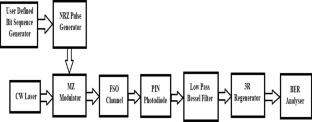
Performance analysis of hybrid free space optical and visible light communications for underwater applications using spatial diversity
Islam Zakaria, Mohamed Abaza, … Moustafa H. Aly

Characterization and Performance Investigation of Underwater Optical Wireless Communication in Static Channels
Himanshu Thakur, C. T. Manimegalai, … Afaan Iliyas

OCDMA transmission-based underwater wireless optical communication system: performance analysis
Somia A. Abd El-Mottaleb, Mehtab Singh, … Moustafa H. Aly
Data Availability
Not Applicable.
Yasir, S. M., Abas, N., Rauf, S., Chaudhry, N. R., & Saleem, M. S. (2022). Investigation of optimum FSO communication link using different modulation techniques under fog conditions. Heliyon, 8 (12), e12516.
Article PubMed PubMed Central Google Scholar
Singh, H., & Chechi, D. P. (2019). Performance evaluation of free space optical (FSO) communication link: effects of rain, snow and fog. In 2019 6th international conference on signal processing and integrated networks (SPIN) . IEEE.
Immadi, G., Venkata Narayana, M., Kotamraju, S. K., & Sree Madhuri, A. (2018). Estimating the performance of free space optical link under adverse weather conditions by using various models. Wireless Personal Communications, 103 , 1603–1613.
Article Google Scholar
Sree Madhuri, A., Immadi, G., & Narayana, M. V. (2020). Estimation of effect of fog on terrestrial free space optical communication link. Wireless Personal Communications, 112 (2), 1229–1241.
Verma, G. D., Mathur, A., & Yadav, P. K. (2022). Experimental investigation of FSO systems under the effect of atmospheric turbulence, heat, and fog. In 2022 IEEE 33rd annual international symposium on personal, indoor and mobile radio communications (PIMRC) . IEEE.
Khan, A. N., Saeed, S., Naeem, Y., Zubair, M., Massoud, Y., & Younis, U. (2022). Atmospheric turbulence and fog attenuation effects in controlled environment FSO communication links. IEEE Photonics Technology Letters, 34 (24), 1341–1344.
Article ADS Google Scholar
Prlinčević, B. P., & Spalević, P. C. (2016). Performances of the image transmission over FSO channel in the last-mile connection. In 2016 24th telecommunications forum (TELFOR) . IEEE.
Djir, A., Meskine, F., & Tayebi, M. L. (2022). Free space optical communication study for image transmission under foggy conditions. In 2022 2nd international conference on advanced electrical engineering (ICAEE) . IEEE.
Soh, M. Y., Ng, W. X., Zou, Q., Lee, D., Teo, T. H., & Yeo, K. S. (2018). Real-time audio transmission using visible light communication. In TENCON 2018–2018 IEEE region 10 conference . IEEE.
Mali, S., Agarwal, A., Singh, S. K., & Pradhan, D. D. (2020). Design and implementation of text and audio signal transmission using visible light communication. In 2020 fourth international conference on I-SMAC (IoT in social, mobile, analytics and cloud) (I-SMAC) . IEEE.
Oubei, H. M., Shen, C., Park, K. H., Kammoun, A., Ng, T. K., Alouini, M. S., & Ooi, B. S. (2017). Underwater wireless optical communications: from system-level demonstrations to channel modelling. In 2017 22nd microoptics conference (MOC) . IEEE.
Arvanitakis, G. N., Bian, R., McKendry, J. J., Cheng, C., Xie, E., He, X., Yang, G., Islim, M. S., Purwita, A. A., Gu, E., Haas, H., & Dawson, M. D. (2019). Gb/s underwater wireless optical communications using series-connected GaN micro-LED arrays. IEEE Photonics Journal, 12 (2), 1–10.
Oubei, H. M., Shen, C., Kammoun, A., Zedini, E., Park, K. H., Sun, X., Liu, G., Kang, C. H., Ng, T. K., Alouini, M. S., & Ooi, B. S. (2018). Light based underwater wireless communications. Japanese Journal of applied physics, 57 (8S2), 08PA06.
Saeed, N., Celik, A., Al-Naffouri, T. Y., & Alouini, M. S. (2019). Underwater optical wireless communications, networking, and localization: A survey. Ad Hoc Networks, 94 , 101935.
Al-Halafi, A., Oubei, H. M., Ooi, B. S., & Shihada, B. (2017). Real-time video transmission over different underwater wireless optical channels using a directly modulated 520 nm laser diode. Journal of Optical Communications and Networking, 9 (10), 826–832.
Nabavi, P., & Yuksel, M. (2019). Performance analysis of air-to-water optical wireless communication using spads. In 2019 IEEE global communications conference (GLOBECOM) . IEEE.
Nguyen, C. T., Nguyen, M. T., & Mai, V. V. (2020). Underwater optical wireless communication-based IoUT networks: MAC performance analysis and improvement. Optical Switching and Networking, 37 , 100570.
Wang, X., Zhang, M., Zhou, H., & Ren, X. (2021). Performance analysis and design considerations of the shallow underwater optical wireless communication system with solar noises utilizing a photon tracing-based simulation platform. Electronics, 10 (5), 632.
Levidala, B. K., Ramavath, P. N., & Krishnan, P. (2021). Performance enhancement using multiple input multiple output in dual-hop convergent underwater wireless optical communication–free-space optical communication system under strong turbulence with pointing errors. Optical Engineering, 60 (10), 106106–106106.
Chen, L.-K., Shao, Y., & Di, Y. (2022). Underwater and water-air optical wireless communication. Journal of Lightwave Technology, 40 (5), 1440–1452.
Article ADS CAS Google Scholar
Bismi, B. S., & Azeem, S. (2023). Design and analysis of DPSK, QPSK modulations in underwater optical communication using free space optics. Wireless Personal Communications, 132 (2), 1487–1502.
Fang, C., Li, S., Wang, Y., & Wang, K. (2023). High-speed underwater optical wireless communication with advanced signal processing methods survey. Photonics, 10 (7), 811.
Xu, Z., Xu, G., & Zheng, Z. (2021). BER and channel capacity performance of an FSO communication system over atmospheric turbulence with different types of noise. Sensors, 21 (10), 3454.
Article ADS PubMed PubMed Central Google Scholar
Esmail, M. A. (2021). Experimental performance evaluation of weak turbulence channel models for FSO links. Optics Communications, 486 , 126776.
Article CAS Google Scholar
Krishnan, P. (2019). Performance analysis of FSO systems over atmospheric turbulence channel for Indian weather conditions. In R. Barille (Ed.), Turbulence and related phenomena . London, UK: IntechOpen.
Google Scholar
Al-Gailani, S. A., Salleh, M. F. M., Salem, A. A., Shaddad, R. Q., Sheikh, U. U., Algeelani, N. A., & Almohamad, T. A. (2020). A survey of free space optics (FSO) communication systems, links, and networks. IEEE Access, 9 , 7353–7373.
Ijaz, M., Ghassemlooy, Z., Le-minh, H., Zvanovec, S., Perez, J., Pesek, J., & Fiser, O. (2013). Experimental validation of fog models for FSO under laboratory-controlled conditions. In 2013 IEEE 24th annual international symposium on personal, indoor, and mobile radio communications (PIMRC) . IEEE.
Schirripa Spagnolo, G., Cozzella, L., & Leccese, F. (2020). Underwater optical wireless communications: Overview. Sensors, 20 (8), 2261.
Ojediran, O. A., Ponnle, A. A., & Oyetunji, S. A. (2022). Experimental study on transmission of visible light in table salt water and effect on underwater wireless optical communication. European Journal of Electrical Engineering and Computer Science, 6 (2), 25–32.
Ponnle, A. A., Ojediran, O. A., & Oyetunji, S. A. (2022). An alternative experimental method for determination of light beam attenuation coefficient in underwater wireless optical communication. European Journal of Electrical Engineering and Computer Science, 6 (3), 19–26.
Artificial Seawater ASTM D-1141-98. ArtificialSeawater.com.
Download references
Author information
Authors and affiliations.
Department of Electronics and Communication Engineering, Madanapalle Institute of Technology and Science, Madanapalle, India
Anbarasi Kannan, V. Bhavana, S. Mohammad Younus & S. Mujeebur Rehaman
Department of Electronics and Communication Engineering, National Institute of Technology Karnataka, Surathkal, India
Prabu Krishnan
You can also search for this author in PubMed Google Scholar
Contributions
1. Paper Writing—VB, SMY, SMR. 2. Figures and table preparation—VB, SMY, SMR. 3. Experimental demonstration and simulation results—VB, SMY, SMR, AK, PK. 4. Review the manuscript—AK, PK.
Corresponding author
Correspondence to Anbarasi Kannan .
Ethics declarations
Conflict of interest.
The authors declare that they have no conflict of interest.
Additional information
Publisher's note.
Springer Nature remains neutral with regard to jurisdictional claims in published maps and institutional affiliations.
Rights and permissions
Springer Nature or its licensor (e.g. a society or other partner) holds exclusive rights to this article under a publishing agreement with the author(s) or other rightsholder(s); author self-archiving of the accepted manuscript version of this article is solely governed by the terms of such publishing agreement and applicable law.
Reprints and permissions
About this article
Kannan, A., Bhavana, V., Younus, S.M. et al. Experimental Demonstration and Performance Analysis of Free Space and Underwater Optical Wireless Communication Systems. Wireless Pers Commun (2024). https://doi.org/10.1007/s11277-024-10887-w
Download citation
Accepted : 28 January 2024
Published : 27 February 2024
DOI : https://doi.org/10.1007/s11277-024-10887-w
Share this article
Anyone you share the following link with will be able to read this content:
Sorry, a shareable link is not currently available for this article.
Provided by the Springer Nature SharedIt content-sharing initiative
- Free space optical communication
- Underwater wireless optical communication
- Bit error rate
- Find a journal
- Publish with us
- Track your research
- Architecture and Design
- Asian and Pacific Studies
- Business and Economics
- Classical and Ancient Near Eastern Studies
- Computer Sciences
- Cultural Studies
- Engineering
- General Interest
- Geosciences
- Industrial Chemistry
- Islamic and Middle Eastern Studies
- Jewish Studies
- Library and Information Science, Book Studies
- Life Sciences
- Linguistics and Semiotics
- Literary Studies
- Materials Sciences
- Mathematics
- Social Sciences
- Sports and Recreation
- Theology and Religion
- Publish your article
- The role of authors
- Promoting your article
- Abstracting & indexing
- Publishing Ethics
- Why publish with De Gruyter
- How to publish with De Gruyter
- Our book series
- Our subject areas
- Your digital product at De Gruyter
- Contribute to our reference works
- Product information
- Tools & resources
- Product Information
- Promotional Materials
- Orders and Inquiries
- FAQ for Library Suppliers and Book Sellers
- Repository Policy
- Free access policy
- Open Access agreements
- Database portals
- For Authors
- Customer service
- People + Culture
- Journal Management
- How to join us
- Working at De Gruyter
- Mission & Vision
- De Gruyter Foundation
- De Gruyter Ebound
- Our Responsibility
- Partner publishers
Your purchase has been completed. Your documents are now available to view.
Free space optical communication in Indian cities; channel characteristics and link performance
Free Space Optical (FSO) communication systems, offering high-speed and high-bandwidth transmission, have emerged as a possible substitute for conventional wired and wireless communication systems. However, FSO links are susceptible to atmospheric deficiencies including attenuation, scintillation, and turbulence, which may severely impact the performance of the communication link. In this research paper, we propose and analyze the performance of a 25 Gbps dual-polarization quadrature phase shift keying (DP-QPSK) coherent optical orthogonal frequency division multiplexing (CO-OFDM)-based FSO communication link with spatial diversity technique under various climatic conditions in four different geographical locations of India, i.e., Delhi, Ahmedabad, Kolkata, and Chennai in the year 2021. The proposed FSO communication system is evaluated through performance analysis and parametric evaluation under various weather conditions such as clear sky, fog, haze, rain, cloud, and thermal gradient. Key performance metrics such as bit error rate (BER), Q-factor, signal-to-noise ratio (SNR), received power, communication range, and reliability are analyzed based on the simulation results. The proposed FSO communication system provides high data rates, improved power efficiency, better resilience to atmospheric impairments, reliable communication links under different weather conditions, and a practical solution for high-speed and high-bandwidth communication in various applications.
Author contributions: All the authors have accepted responsibility for the entire content of this submitted manuscript and approved submission.
Research funding: None declared.
Conflict of interest statement: The authors declare no conflicts of interest regarding this article.
1. Al-Gailani, SA, Salleh, MF, Salem, AA, Shaddad, RQ, Sheikh, UU, Algeelani, NA, et al.. A survey of free space optics (FSO) communication systems, links and networks. IEEE Access 2020;9:7353–73. https://doi.org/10.1109/access.2020.3048049 . Search in Google Scholar
2. Khalighi, MA, Uysal, M. Survey on free space optical communication: a communication theory perspective. Commun Surv Tutorials, IEEE 2014;16:2231–58. https://doi.org/10.1109/comst.2014.2329501 . Search in Google Scholar
3. Kaushal, H, Kaddoum, G. Optical communication in space: challenges and mitigation techniques. Commun Surv Tutorials, IEEE 2016;19:57–96. https://doi.org/10.1109/comst.2016.2603518 . Search in Google Scholar
4. Kshatriya, AJ, Acharya, YB, Aggarwal, AK, Majumdar, AK. Estimation of FSO link availability using climatic data. J Opt 2016;45:324–30. https://doi.org/10.1007/s12596-016-0327-4 . Search in Google Scholar
5. Shah, S, Mughal, S, Hira, N, Bhatti, MI, Kazi, H. Visibility statistics based unavailability events estimation of FSO link due to fog in four cities of Pakistan. In: International conference on emerging technologies (ICET). Piscataway . Islamabad, Pakistan: IEEE; 2014:1–5 pp. 10.1109/ICET.2013.6743505 Search in Google Scholar
6. Immadi, G, Narayana, MV, Kotamraju, SK, Madhuri, AS. Estimating the performance of free space optical link under adverse weather conditions by using various models. Wireless Pers Commun 2018;103:1603–13. https://doi.org/10.1007/s11277-018-5870-7 . Search in Google Scholar
7. Naresh, K, Antonio Luis, JT. 10 Gbit/s OFDM based FSO communication system using M-QAM modulation with enhanced detection. Opt Quant Electron 2015;48:9–16. 10.1007/s11082-015-0272-5 Search in Google Scholar
8. Badar, N, Jha, RK, Towfeeq, I. Performance analysis of an 80 (8310) Gbps RZ-DPSKbased WDM-FSO system under combined effects of various weather conditions and atmospheric turbulence-induced fading employing Gamma–Gamma fading model. Opt Quant Electron 2018;50:44–55. https://doi.org/10.1007/s11082-017-1306-y . Search in Google Scholar
9. Ali, MAA, Shaker, FK, Kadhum, HA. Investigation and analysis of data rate for free space optical communications system under dust conditions. Wireless Pers Commun 2020;113:2327–38. https://doi.org/10.1007/s11277-020-07328-9 . Search in Google Scholar
10. Singh, H, Mittal, N, Miglani, R, Singh, H, Gaba, G, Hedabou, M. Design and analysis of high-speed free space optical (FSO) communication system for supporting fifth generation (5G) data services in diverse geographical locations of India. IEEE Photon J 2021;13:1–12. https://doi.org/10.1109/jphot.2021.3113650 . Search in Google Scholar
11. Ghalot, R, Madhu, C, Kaur, G, Singh, P. Link estimation of different Indian cities under fog weather conditions. Wireless Pers Commun 2019;105:1215–34. https://doi.org/10.1007/s11277-019-06142-2 . Search in Google Scholar
12. Yasir, SM, Abas, N, Rauf, S, Chaudhry, NR, Saleem, MS. Investigation of optimum FSO communication link using different modulation techniques under fog conditions. Heliyon 2022;8:1–14. https://doi.org/10.1016/j.heliyon.2022.e12516 . Search in Google Scholar PubMed PubMed Central
13. Mohale, J, Handura, MR, Olwal, TO, Nyirenda, CN. Feasibility study of free-space optical communication for South Africa. Opt Eng 2016;55:1–10. https://doi.org/10.1117/1.oe.55.5.056108 . Search in Google Scholar
14. Prokes, A. Atmospheric effects on availability of free space optics systems. Opt Eng 2009;48:1–10. 10.1117/1.3155431 Search in Google Scholar
15. Al Naboulsi, MC, Sizun, H, Fornel, FD. Fog attenuation prediction for optical and infrared waves. Opt Eng 2004;43:319–29. https://doi.org/10.1117/1.1637611 . Search in Google Scholar
16. Khan, MS, Naqvi, MR, Khan, MA, Latif, M, Ullah, K, Khan, RD, et al.. Optical attenuation estimation from measured visibility data in Islamabad, Pakistan. In: 8th conference on optical cabling and infrastructure (NOC-OC&I) . Austria: Graz; 2013:203–8 pp. 10.1109/NOC-OCI.2013.6582891 Search in Google Scholar
17. Basahel, A, Rafiqul, IM, Suriza, AZ, Habaebi, MH. Availability analysis of free-space-optical links based on rain rate and visibility statistics from tropical a climate. Optik 2016;127:10316–21. https://doi.org/10.1016/j.ijleo.2016.08.061 . Search in Google Scholar
18. Singh, H, Mittal, N. Performance analysis of free space optical communication system under rain weather conditions: a case study for inland and coastal locations of India. Opt Quant Electron 2021;203:1–21. https://doi.org/10.1007/s11082-021-02848-5 . Search in Google Scholar
19. Singh, M, Bhatia, S, Kaushal, H. Performance evaluation of free space optical link under various weather conditions. In: Proceedings of the second international conference on computer and communication technologies . Noida; 2015:329–42 pp. 10.1007/978-81-322-2517-1_33 Search in Google Scholar
20. Awan, MS, Marzuki, LE, Hillbrand, B, Nadeem, F, Khan, MS. Cloud attenuations for free-space optical links. In: 2009 International workshop on satellite and Space communications . Siena, Italy; 2009:1–5 pp. 10.1109/IWSSC.2009.5286364 Search in Google Scholar
21. Bhatt, P, Sedani, B, Kotak, N. Designing and simulation of 30Gbps FSO communication link under different atmospheric and cloud conditions. Int J Eng Trends Technol 2021;69:228–34. https://doi.org/10.14445/22315381/ijett-v69i5p229 . Search in Google Scholar
22. Handura, MR, Ndjavera, KM, Nyirenda, CN, Olwal, TO. Determining the feasibility of free space optical communication in Namibia. Opt Commun 2016;366:425–30. https://doi.org/10.1016/j.optcom.2015.12.057 . Search in Google Scholar
23. Chauhan, S, Miglani, R, Kansal, L, Gaba, GS, Masud, M. Performance analysis and enhancement of FreeSpace optical links for developing state-of-the-art smart city framework. MDPI Photonics 2020;7:1–16. https://doi.org/10.3390/photonics7040132 . Search in Google Scholar
24. Padhy, JB, Patnaik, B. CO-OFDM and DP-QPSK based DWDM optical wireless communication system. DE GRUYTER. J Opt Commun 2018;72:1–13. Search in Google Scholar
25. Mehtab, S, Jyoteesh, M, Mani Rajan, MS, Vigneswaran, Moustafa, HA. A long-haul 100 Gbps hybrid PDM/CO-OFDM FSO transmission system: impact of climate conditions and atmospheric turbulence. Alex Eng J 2020;60:785–94. 10.1016/j.aej.2020.10.008 Search in Google Scholar
© 2023 Walter de Gruyter GmbH, Berlin/Boston
- X / Twitter
Supplementary Materials
Please login or register with De Gruyter to order this product.
IMAGES
VIDEO
COMMENTS
Abstract: The next generation (NG) optical technologies will unveil certain unique features, namely ultra-high data rate, broadband multiple services, scalable bandwidth, and flexible communications for manifold end-users. Among the optical technologies, free space optical (FSO) technology is a key element to achieve free space data transmission according to the requirements of the future ...
Consequently, free-space optical communication (FSOC) with its high data transfer rate, strong security, and low power consumption, holds promising potential as the primary means for space ...
Free Space Optics (FSO) is an optical communication technique which disseminates light in free space such as air, vacuum or celestial space, to wirelessly transfer data. FSO communication offers high data rates up to 2.5 Gbps over a range of 100 m to a few kilometers and has the potential to replace the traditional means of communications in a wide variety of applications. Despite advantages ...
Free space optical communication (FSO) refers to the point-to-point wireless optical transmission through the unguided propagation media using infrared (IR) and visible light bands. Generally, outdoor FSO links operate in the VL and UV bands, near IR and VL bands are used in indoor and underwater FSO communication ( Hamza et al., 2019 ).
Chen, C. et al. Demonstration of a bidirectional coherent air-to-ground optical link. In Free-Space Laser Communication and Atmospheric Propagation XXX Vol. 10524 (eds Hemmati, H. & Boroson, D. M ...
There is growing interest in the mid-IR region for potential applications in communications, sensing, and imaging in both free space and fiber 1,2,3.For free-space optical communication links, the ...
In this paper Free Space Optical communication concept will be introduced. In addition, the performance of FSO communication link will analysis and illustrates its main challenges and it possible ...
Free Space Optics (FSO) is an optical communication technique which disseminates light in free space such as air, vacuum or celestial space, to wirelessly transfer data. ... and potential directions for future research endeavors. This paper presents a state-of-the- ... Fig. 1 Conceptual topology of Free Space Optical (FSO) integrated network ...
With its high data transmission capability comparable to fiber optics and its ability to operate in the interference-free optical spectrum, free space optical (FSO) communication is ideally suited to backhauling requirements in NTNs. In this paper, we present a comprehensive tutorial on airborne FSO backhauling.
The demand for large bandwidth and high data rates in communication systems has become the main cause of the upgrade of traditional networks into free space optical (FSO) technology. FSO technology has gained significant popularity due to its easy deployment, high data rates, abundant bandwidth, enhanced security, and license-free spectrum utilization. However, the performance of FSO ...
The link performance of free space optical communications (FSOC) and deep space optical communications (DSOC) are investigated by considering two scenarios in space communications, for example, for the downlink and uplink between the earth ground stations and the near earth geostationary (GEO) satellites, and between the earth and spacecraft with large distance of 1 astronomical unit (AU) to ...
This paper represents a technological overview of existing optical wireless hybrid networks and discusses optical-based free-space optics, optical camera communication, light fidelity, and light fidelity which extends the concept of visible light communication to attain bi-directional and fully networked wireless communication. Expand
Download a PDF of the paper titled Free Space Optical Communication for Inter-Satellite Link: Architecture, Potentials and Trends, by Guanhua Wang and 3 other authors ... routing and scheduling algorithm, and integrated sensing and communication are discussed to direct future research. Subjects: Systems and Control (eess.SY) Cite as:
as free space optical (FSO) communication. The FSO communication systems are further classied into terrestrial and space optical links that include building-to-building, ground-to-satellite, satellite-to-ground, satellite-to-satellite, satellite-to-airborne platforms (unmanned aerial vehicles (UAVs) or balloons), [10] [12] etc. Fig. 1 ...
Free Space Optics (FSO) is an optical communication technique which disseminates light in free space such as air, vacuum or celestial space, to wirelessly transfer data. FSO communication offers high data rates up to 2.5 Gbps over a range of 100 m to a few kilometers and has the potential to replace the traditional means of communications in a ...
Optical communication modulation technology and networking technology are two important technologies for constructing free-space optical (FSO) communication. In this paper, pulse width modulation (PWM) is used to realize free-space optical communication. The process of signal modulation and demodulation is implemented by means of a field programmable gate array (FPGA). An optical communication ...
During the last two decades, free space optical (FSO) communication systems have been getting research interests due to unlicensed frequency spectrum, very high data rate and ease of connectivity ...
As the limitations of conventional radio communications between satellites and the ground become apparent, various experiments are being conducted around the world to overcome them with space laser communication. In this study, we address the development of our own optical communications terminal (OCT) and optical ground station (OGS) and the experiments of free-space optical communication ...
Free-space optical communication has finally emerged as a key technology for solving the increasing bandwidth limitations for space communication while reducing the size, weight and power of satellite communication systems, and taking advantage of a license-free spectrum. In the last few years, many missions have demonstrated in orbit the ...
This paper proposes a free space optical communication (FSO) receivier system with adaptive alignment based on pure phase holographic imaging. During the frame header transmission period, the optical phased array in this system performs specific holographic imaging on the receiving plane, which assist the system to undergo beam alignment. The system model has been built in this work, along ...
This research paper presents the development and implementation of a real-time communication system that utilizes LEDs for transmitting text, image, and audio through Free Space Optical Communication (FSOC) and Underwater Wireless Optical Communication (UWOC) channels. The impact of atmospheric and oceanic attenuation and turbulences are considered for the performance analysis of the proposed ...
free space from the source to the destination, rather than guided through an optical fiber. Light travels through air faster than it does through glass. So one may regard FSO as optical communications at the speed of light. Without a doubt, optical fiber is the most reliable means of providing optical communications.
Free Space Optical (FSO) communication systems, offering high-speed and high-bandwidth transmission, have emerged as a possible substitute for conventional wired and wireless communication systems. However, FSO links are susceptible to atmospheric deficiencies including attenuation, scintillation, and turbulence, which may severely impact the performance of the communication link. In this ...
Our research provides a reference for optimizing the design of light sources and free-space optical communication system with annular QAVBA. In this paper, we introduce a new type of controllable auto-focusing vortex beam array named annular quasi-Airy vortex beam array (QAVBA), which can reduce the crosstalk among different orbital angular ...