Diagramming Build diagrams of all kinds from flowcharts to floor plans with intuitive tools and templates.
Whiteboarding collaborate with your team on a seamless workspace no matter where they are., data generate diagrams from data and add data to shapes to enhance your existing visuals., enterprise friendly easy to administer and license your entire organization., security see how we keep your data safe., apps & integrations connect to all the tools you use from microsoft, google workspace, atlassian, and more..
- What's New Read about new features and updates.

Product Management Roadmap features, brainstorm, and report on development, so your team can ship features that users love.
Software engineering design and maintain complex systems collaboratively., information technology visualize system architecture, document processes, and communicate internal policies., sales close bigger deals with reproducible processes that lead to successful onboarding and training..
- Getting Started Learn how to make any type of visual with SmartDraw. Familiarize yourself with the UI, choosing templates, managing documents, and more.
- Templates get inspired by browsing examples and templates available in SmartDraw.
Diagrams Learn about all the types of diagrams you can create with SmartDraw.
Whiteboard learn how to combine free-form brainstorming with diagram blueprints all while collaborating with your team., data visualizers learn how to generate visuals like org charts and class diagrams from data., development platform browse built-in data visualizers and see how you can build your own custom visualization., open api the smartdraw api allows you to skip the drawing process and generate diagrams from data automatically., shape data add data to shapes, import data, export manifests, and create data rules to change dashboards that update..
- Explore SmartDraw Check out useful features that will make your life easier.
- Blog Read articles about best practices, find tips on collaborating, learn to give better presentations and more.
Support Search through SmartDraw's knowledge base, view frequently asked questions, or contact our support team.
Site license site licenses start as low as $2,995 for your entire organization..
- Team License The SmartDraw team License puts you in control with powerful administrative features.
Apps & Integrations Connect to all the tools you use.
- Contact Sales
What's New?
Solutions By Team
Save money, reduce hassle, and get more.
Unleash your team's productivity by combining enterprise-class diagramming, whiteboarding, and data while saving 10x over Visio and Lucidchart!
Getting Started Learn to make visuals, familiarize yourself with the UI, choosing templates, managing documents, and more.
Templates get inspired by browsing examples and templates available in smartdraw., developer resources, additional resources.

Team License The SmartDraw Team License puts you in control with powerful administrative features.
Solutions for your team.
UML Diagram
Quickly create uml diagrams from data or smartdraw's built-in templates, what is a uml diagram, what is meant by uml, uml diagram tutorial, types of uml diagrams, uml diagram symbols, why do we use uml, diagrams from data, uml diagram examples, with smartdraw, you can create many different types of diagrams, charts, and visuals.
UML is a way of visualizing a software program using a collection of diagrams. The notation has evolved from the work of Grady Booch, James Rumbaugh, Ivar Jacobson, and the Rational Software Corporation to be used for object-oriented design, but it has since been extended to cover a wider variety of software engineering projects. Today, UML is accepted by the Object Management Group (OMG) as the standard for modeling software development.
UML stands for Unified Modeling Language. UML 2.0 helped extend the original UML specification to cover a wider portion of software development efforts including agile practices.
- Improved integration between structural models like class diagrams and behavior models like activity diagrams.
- Added the ability to define a hierarchy and decompose a software system into components and sub-components.
- The original UML specified nine diagrams; UML 2.x brings that number up to 13. The four new diagrams are called: communication diagram, composite structure diagram, interaction overview diagram, and timing diagram. It also renamed statechart diagrams to state machine diagrams, also known as state diagrams.
The key to making a UML diagram is connecting shapes that represent an object or class with other shapes to illustrate relationships and the flow of information and data. To learn more about creating UML diagrams:
- Read Our UML Diagram Tutorial
- Browse Tips for Better UML Diagrams
The current UML standards call for 13 different types of diagrams: class, activity, object, use case, sequence, package, state, component, communication, composite structure, interaction overview, timing, and deployment.
These diagrams are organized into two distinct groups: structural diagrams and behavioral or interaction diagrams.
Structural UML diagrams
- Class diagram
- Package diagram
- Object diagram
- Component diagram
- Composite structure diagram
- Deployment diagram
Behavioral UML diagrams
- Activity diagram
- Sequence diagram
- Use case diagram
- State diagram
- Communication diagram
- Interaction overview diagram
- Timing diagram
Class Diagram Class diagrams are the backbone of almost every object-oriented method, including UML. They describe the static structure of a system. Learn more
Package Diagram Package diagrams are a subset of class diagrams, but developers sometimes treat them as a separate technique. Package diagrams organize elements of a system into related groups to minimize dependencies between packages.
Object Diagram Object diagrams describe the static structure of a system at a particular time. They can be used to test class diagrams for accuracy.
Composite Structure Diagram Composite structure diagrams show the internal part of a class.
Use Case Diagram Use case diagrams model the functionality of a system using actors and use cases. Learn more
Activity Diagram Activity diagrams illustrate the dynamic nature of a system by modeling the flow of control from activity to activity. An activity represents an operation on some class in the system that results in a change in the state of the system. Typically, activity diagrams are used to model workflow or business processes and internal operation. Learn more
Sequence Diagram Sequence diagrams describe interactions among classes in terms of an exchange of messages over time. Learn more
Interaction Overview Diagram Interaction overview diagrams are a combination of activity and sequence diagrams. They model a sequence of actions and let you deconstruct more complex interactions into manageable occurrences. You should use the same notation on interaction overview diagrams that you would see on an activity diagram.
Timing Diagram A timing diagram is a type of behavioral or interaction UML diagram that focuses on processes that take place during a specific period of time. They're a special instance of a sequence diagram, except time is shown to increase from left to right instead of top down.
Communication Diagram Communication diagrams model the interactions between objects in sequence. They describe both the static structure and the dynamic behavior of a system. In many ways, a communication diagram is a simplified version of a collaboration diagram introduced in UML 2.0.
State Diagram Statechart diagrams , now known as state machine diagrams and state diagrams describe the dynamic behavior of a system in response to external stimuli. State diagrams are especially useful in modeling reactive objects whose states are triggered by specific events. Learn more
Component Diagram Component diagrams describe the organization of physical software components, including source code, run-time (binary) code, and executables. Learn more .
Deployment Diagram Deployment diagrams depict the physical resources in a system, including nodes, components, and connections.
There are many different types of UML diagrams and each has a slightly different symbol set.
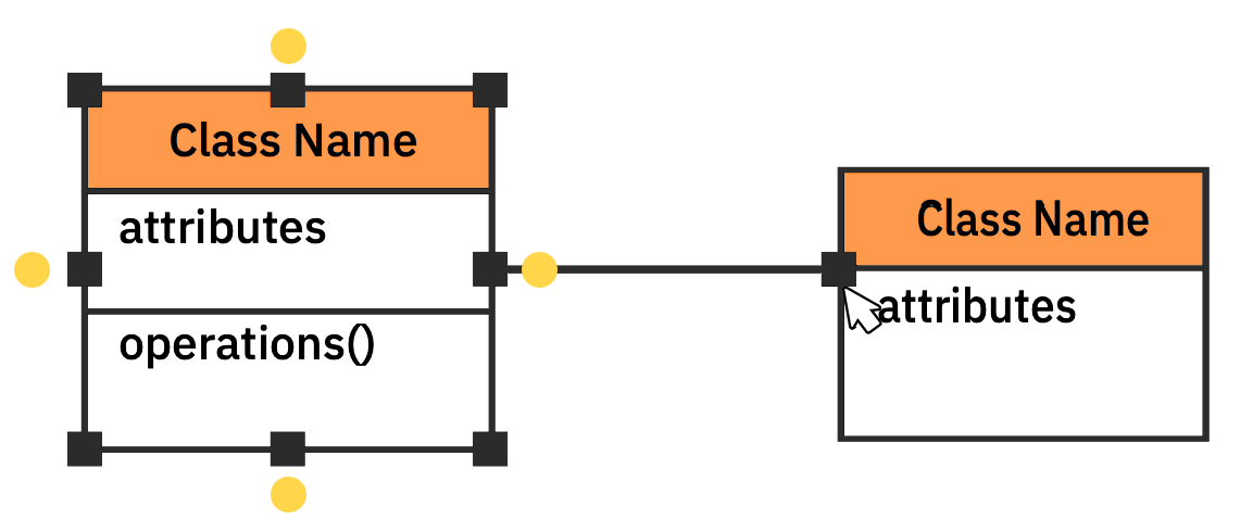
Class diagrams are perhaps one of the most common UML diagrams used and class diagram symbols center around defining attributes of a class. For example, there are symbols for active classes and interfaces. A class symbol can also be divided to show a class's operations, attributes, and responsibilities.
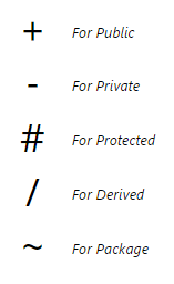
Visibility of any class members are marked by notations of
Lines are also important symbols to denote relationships between components. Generalization and Inheritance are denoted with empty arrowheads. Composition is shown with a filled in diamond. Aggregation is shown with an empty diamond. Dependencies are marked with a dashed line with an arrow. Using > allows you to indicate properties of that dependency. Multiplicity is usually shown with a number at one end of the arrow and a * at the other.
Package diagrams have symbols defining a package that look like a folder.
Activity diagrams have symbols for activities, states, including separate symbols for an initial state and a final state. The control flow is usually shown with an arrow and the object flow is shown with a dashed arrow.
Use case diagrams have symbols for actors and use cases.
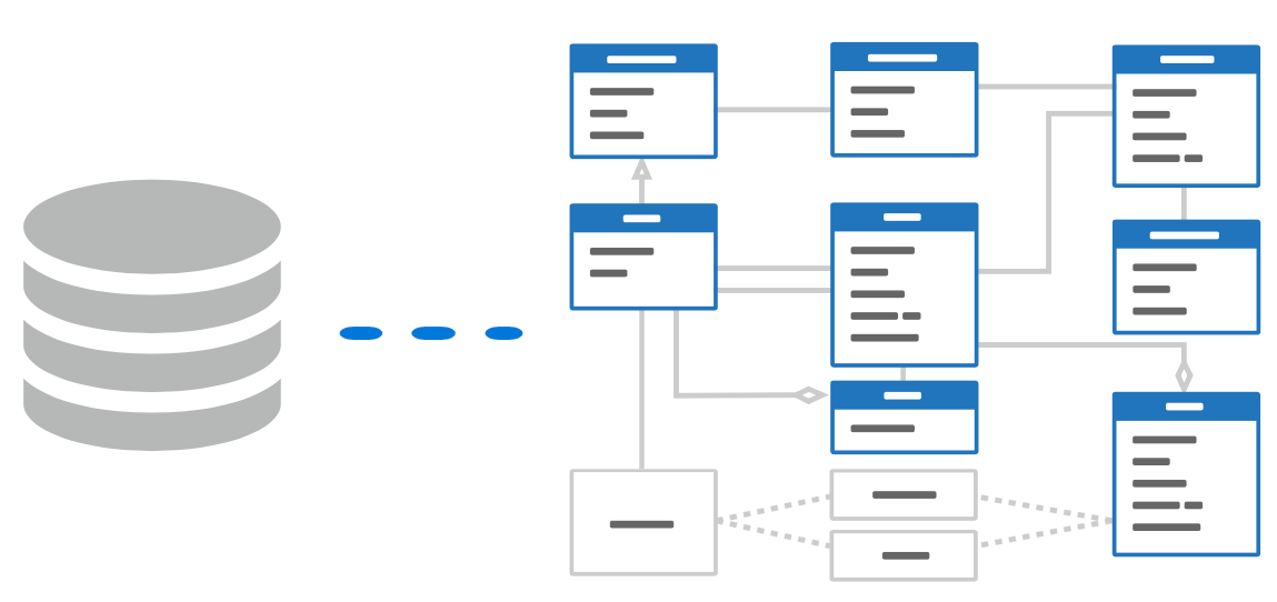
A complex enterprise application with many collaborators will require a solid foundation of planning and clear, concise communication among team members as the project progresses.
Visualizing user interactions, processes, and the structure of the system you're trying to build will help save time down the line and make sure everyone on the team is on the same page.
Diagrams from Data
SmartDraw has an extension to generate UML class diagrams automatically using a GitHub repo or a local repository. Learn more about how to build a class diagram without drawing at all using SmartDraw's Class Diagram Extension.
You can also write your own extension to generate other UML and software design diagrams using SmartDraw's Open API. Learn more.
The best way to understand UML is to look at some examples of UML diagrams.
Click on any of these UML diagrams included in SmartDraw and edit them:
Browse SmartDraw's entire collection of UML diagram examples and templates
More UML Diagram Information
- UML diagram tool
- Software design diagram templates
- Data flow diagram software
- Visio ® alternative
- Lucidchart alternative
- SmartDraw reviews
- Deployment chart software
- Diagram tool
- Game design software
- Visio ® import
- SmartDraw for Mac
Try SmartDraw's UML Diagram Software Free
Discover why SmartDraw is the best UML diagram software today.
- System Design Tutorial
- What is System Design
- System Design Life Cycle
- High Level Design HLD
- Low Level Design LLD
- Design Patterns
- UML Diagrams
- System Design Interview Guide
- Crack System Design Round
- System Design Bootcamp
- System Design Interview Questions
- Microservices
- Scalability
- What is High Level Design – Learn System Design
- Horizontal and Vertical Scaling | System Design
- Availability in System Design
- Consistency in System Design
- Reliability in System Design
- CAP Theorem in System Design
- Difference between Concurrency and Parallelism
- What is Load Balancer & How Load Balancing works?
- What is Content Delivery Network(CDN) in System Design
- Caching - System Design Concept
- Message Queues | System Design
- Communication Protocols In System Design
- Network Protocols and Proxies in System Design
Unified Modeling Language (UML) Diagrams
Unified Modeling Language (UML) is a general-purpose modeling language. The main aim of UML is to define a standard way to visualize the way a system has been designed. It is quite similar to blueprints used in other fields of engineering. UML is not a programming language , it is rather a visual language.
- We use UML diagrams to portray the behavior and structure of a system.
- UML helps software engineers, businessmen, and system architects with modeling, design, and analysis.
- The Object Management Group (OMG) adopted Unified Modelling Language as a standard in 1997. It’s been managed by OMG ever since.
- The International Organization for Standardization (ISO) published UML as an approved standard in 2005. UML has been revised over the years and is reviewed periodically.

Important Topics for the UML Diagrams
- Why do we need UML?
- Different Types of UML Diagrams
- Structural UML Diagrams
- Behavioral UML Diagrams
- Object-Oriented Concepts Used in UML Diagrams
- Tools for creating UML Diagrams
- Steps to create UML Diagrams
- UML diagrams best practices
- UML and Agile Development
- Common Challenges in UML Modeling:
1. Why do we need UML?
- Complex applications need collaboration and planning from multiple teams and hence require a clear and concise way to communicate amongst them.
- Businessmen do not understand code. So UML becomes essential to communicate with non-programmers about essential requirements, functionalities, and processes of the system.
- A lot of time is saved down the line when teams can visualize processes, user interactions, and the static structure of the system.
2. Different Types of UML Diagrams
UML is linked with object-oriented design and analysis. UML makes use of elements and forms associations between them to form diagrams. Diagrams in UML can be broadly classified as:

3. Structural UML Diagrams
3.1. class diagram.
The most widely use UML diagram is the class diagram. It is the building block of all object oriented software systems. We use class diagrams to depict the static structure of a system by showing system’s classes, their methods and attributes. Class diagrams also help us identify relationship between different classes or objects.
3.2. Composite Structure Diagram
We use composite structure diagrams to represent the internal structure of a class and its interaction points with other parts of the system.
- A composite structure diagram represents relationship between parts and their configuration which determine how the classifier (class, a component, or a deployment node) behaves.
- They represent internal structure of a structured classifier making the use of parts, ports, and connectors.
- We can also model collaborations using composite structure diagrams.
- They are similar to class diagrams except they represent individual parts in detail as compared to the entire class.
3.3. Object Diagram
An Object Diagram can be referred to as a screenshot of the instances in a system and the relationship that exists between them. Since object diagrams depict behaviour when objects have been instantiated, we are able to study the behaviour of the system at a particular instant.
- An object diagram is similar to a class diagram except it shows the instances of classes in the system.
- We depict actual classifiers and their relationships making the use of class diagrams.
- On the other hand, an Object Diagram represents specific instances of classes and relationships between them at a point of time.
3.4. Component Diagram
Component diagrams are used to represent how the physical components in a system have been organized. We use them for modelling implementation details.
- Component Diagrams depict the structural relationship between software system elements and help us in understanding if functional requirements have been covered by planned development.
- Component Diagrams become essential to use when we design and build complex systems.
- Interfaces are used by components of the system to communicate with each other.
3.5. Deployment Diagram
Deployment Diagrams are used to represent system hardware and its software.It tells us what hardware components exist and what software components run on them.
- We illustrate system architecture as distribution of software artifacts over distributed targets.
- An artifact is the information that is generated by system software.
- They are primarily used when a software is being used, distributed or deployed over multiple machines with different configurations.
3.6. Package Diagram
We use Package Diagrams to depict how packages and their elements have been organized. A package diagram simply shows us the dependencies between different packages and internal composition of packages.
- Packages help us to organise UML diagrams into meaningful groups and make the diagram easy to understand.
- They are primarily used to organise class and use case diagrams.
4. Behavioral UML Diagrams
4.1. state machine diagrams.
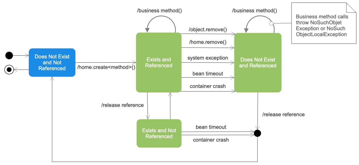
A state diagram is used to represent the condition of the system or part of the system at finite instances of time. It’s a behavioral diagram and it represents the behavior using finite state transitions.
- State diagrams are also referred to as State machines and State-chart Diagrams
- These terms are often used interchangeably. So simply, a state diagram is used to model the dynamic behavior of a class in response to time and changing external stimuli.
4.2. Activity Diagrams
We use Activity Diagrams to illustrate the flow of control in a system. We can also use an activity diagram to refer to the steps involved in the execution of a use case.
- We model sequential and concurrent activities using activity diagrams. So, we basically depict workflows visually using an activity diagram.
- An activity diagram focuses on condition of flow and the sequence in which it happens.
- We describe or depict what causes a particular event using an activity diagram.
4.3. Use Case Diagrams
Use Case Diagrams are used to depict the functionality of a system or a part of a system. They are widely used to illustrate the functional requirements of the system and its interaction with external agents(actors).
- A use case is basically a diagram representing different scenarios where the system can be used.
- A use case diagram gives us a high level view of what the system or a part of the system does without going into implementation details.
4.4. Sequence Diagram
A sequence diagram simply depicts interaction between objects in a sequential order i.e. the order in which these interactions take place.
- We can also use the terms event diagrams or event scenarios to refer to a sequence diagram.
- Sequence diagrams describe how and in what order the objects in a system function.
- These diagrams are widely used by businessmen and software developers to document and understand requirements for new and existing systems.
4.5. Communication Diagram
A Communication Diagram (known as Collaboration Diagram in UML 1.x) is used to show sequenced messages exchanged between objects.
- A communication diagram focuses primarily on objects and their relationships.
- We can represent similar information using Sequence diagrams, however communication diagrams represent objects and links in a free form.
4.6. Timing Diagram
Timing Diagram are a special form of Sequence diagrams which are used to depict the behavior of objects over a time frame. We use them to show time and duration constraints which govern changes in states and behavior of objects.
4.7. Interaction Overview Diagram
An Interaction Overview Diagram models a sequence of actions and helps us simplify complex interactions into simpler occurrences. It is a mixture of activity and sequence diagrams.
5. Object-Oriented Concepts Used in UML Diagrams
- Class: A class defines the blue print i.e. structure and functions of an object.
- Objects : Objects help us to decompose large systems and help us to modularize our system. Modularity helps to divide our system into understandable components so that we can build our system piece by piece.
- Inheritance: Inheritance is a mechanism by which child classes inherit the properties of their parent classes.
- Abstraction: Abstraction in UML refers to the process of emphasizing the essential aspects of a system or object while disregarding irrelevant details. By abstracting away unnecessary complexities, abstraction facilitates a clearer understanding and communication among stakeholders.
- Encapsulation: Binding data together and protecting it from the outer world is referred to as encapsulation.
- Polymorphism: Mechanism by which functions or entities are able to exist in different forms.
5.1. Additions in UML 2.0
- Software development methodologies like agile have been incorporated and scope of original UML specification has been broadened.
- Originally UML specified 9 diagrams. UML 2.x has increased the number of diagrams from 9 to 13. The four diagrams that were added are : timing diagram, communication diagram, interaction overview diagram and composite structure diagram. UML 2.x renamed statechart diagrams to state machine diagrams.
- UML 2.x added the ability to decompose software system into components and sub-components.
6. Tools for creating UML Diagrams
There are several tools available for creating Unified Modeling Language (UML) diagrams, which are commonly used in software development to visually represent system architecture, design, and implementation. Here are some popular UML diagram creating tools:
- Lucidchart: Lucidchart is a web-based diagramming tool that supports UML diagrams. It’s user-friendly and collaborative, allowing multiple users to work on diagrams in real-time.
- Draw.io: Draw.io is a free, web-based diagramming tool that supports various diagram types, including UML. It integrates with various cloud storage services and can be used offline.
- Visual Paradigm: Visual Paradigm provides a comprehensive suite of tools for software development, including UML diagramming. It offers both online and desktop versions and supports a wide range of UML diagrams.
- StarUML: StarUML is an open-source UML modeling tool with a user-friendly interface. It supports the standard UML 2.x diagrams and allows users to customize and extend its functionality through plugins.
- Papyrus: Papyrus is an open-source UML modeling tool that is part of the Eclipse Modeling Project. It provides a customizable environment for creating, editing, and visualizing UML diagrams.
- PlantUML: PlantUML is a text-based tool that allows you to create UML diagrams using a simple and human-readable syntax. It’s often used in conjunction with other tools and supports a variety of diagram types.
7. Steps to create UML Diagrams

Creating Unified Modeling Language (UML) diagrams involves a systematic process that typically includes the following steps:
- Determine the purpose of creating the UML diagram. Different types of UML diagrams serve various purposes, such as capturing requirements, designing system architecture, or documenting class relationships.
- Identify the key elements (classes, objects, use cases, etc.) and their relationships that need to be represented in the diagram. This step involves understanding the structure and behavior of the system you are modeling.
- Choose the UML diagram type that best fits your modeling needs. Common types include Class Diagrams, Use Case Diagrams, Sequence Diagrams, Activity Diagrams, and more.
- Before using a UML modeling tool, it can be helpful to create a rough sketch on paper or a whiteboard. This can help you visualize the layout and connections between elements.
- Select a UML modeling tool that suits your preferences and requirements. There are various tools available, both online and offline, that offer features for creating and editing UML diagrams.
- Open the selected UML modeling tool and create a new project or diagram. Begin adding elements (e.g., classes, use cases, actors) to the diagram and connect them with appropriate relationships (e.g., associations, dependencies).
- For each element in the diagram, specify relevant properties and attributes. This might include class attributes and methods, use case details, or any other information specific to the diagram type.
- Enhance the clarity of your diagram by adding annotations, comments, and explanatory notes. This helps anyone reviewing the diagram to understand the design decisions and logic behind it.
- Review the diagram for accuracy and completeness. Ensure that the relationships, constraints, and elements accurately represent the intended system or process. Validate your diagram against the requirements and make necessary adjustments.
- Refine the diagram based on feedback and additional insights. UML diagrams are often created iteratively as the understanding of the system evolves.
- Some UML tools allow you to generate documentation directly from your diagrams. This can include class documentation, use case descriptions, and other relevant information.
Note: Remember that the specific steps may vary based on the UML diagram type and the tool you are using.
8. UML diagrams best practices
Unified Modeling Language (UML) is a powerful tool for visualizing and documenting the design of a system. To create effective and meaningful UML diagrams, it’s essential to follow best practices. Here are some UML best practices:
- Understand the Audience: Consider your audience when creating UML diagrams. Tailor the level of detail and the choice of diagrams to match the understanding and needs of your audience, whether they are developers, architects, or stakeholders.
- Keep Diagrams Simple and Focused: Aim for simplicity in your diagrams. Each diagram should focus on a specific aspect of the system or a particular set of relationships. Avoid clutter and unnecessary details that can distract from the main message.
- Use Consistent Naming Conventions: Adopt consistent and meaningful names for classes, objects, attributes, methods, and other UML elements. Clear and well-thought-out naming conventions enhance the understandability of your diagrams.
- Follow Standard UML Notations: Adhere to standard UML notations and symbols. Consistency in using UML conventions ensures that your diagrams are easily understood by others who are familiar with UML.
- Keep Relationships Explicit: Clearly define and label relationships between elements. Use appropriate arrows, multiplicity notations, and association names to communicate the nature of connections between classes, objects, or use cases.
9. UML and Agile Development
Unified Modeling Language (UML) and Agile development are two different approaches to software development, and they can be effectively integrated to enhance the overall development process. Here are some key points about the relationship between UML and Agile development:
9.1. UML in Agile Development
- Visualization and Communication: UML diagrams provide a visual way to represent system architecture, design, and behavior. In Agile development, where communication is crucial, UML diagrams can serve as effective communication tools between team members, stakeholders, and even non-technical audiences.
- User Stories and Use Cases: UML use case diagrams can be used to capture and model user stories in Agile development. Use cases help in understanding the system from an end-user perspective and contribute to the creation of user stories.
- Iterative Modeling: Agile methodologies emphasize iterative development, and UML can be adapted to support this approach. UML models can be created and refined incrementally as the understanding of the system evolves during each iteration.
- Agile Modeling Techniques: Agile modeling techniques, such as user story mapping and impact mapping, complement UML by providing lightweight ways to visualize and communicate requirements and design. These techniques align with the Agile principle of valuing working software over comprehensive documentation.
9.2. Balancing Agility and Modeling
- Adaptive Modeling: Adopt an adaptive modeling approach where UML is used to the extent necessary for effective communication and understanding. The focus should be on delivering value through working software rather than exhaustive documentation.
- Team Empowerment: Empower the development team to choose the right level of modeling based on the project’s needs. Team members should feel comfortable using UML as a communication tool without feeling burdened by excessive modeling requirements.
10. Common Challenges in UML Modeling
- Time-Intensive: UML modeling can be perceived as time-consuming, especially in fast-paced Agile environments where rapid development is emphasized. Teams may struggle to keep up with the need for frequent updates to UML diagrams.
- Over-Documentation: Agile principles value working software over comprehensive documentation. There’s a risk of over-documentation when using UML, as teams may spend too much time on detailed diagrams that do not directly contribute to delivering value.
- Changing Requirements: Agile projects often face changing requirements, and UML diagrams may become quickly outdated. Keeping up with these changes and ensuring that UML models reflect the current system state can be challenging.
- Collaboration Issues: Agile emphasizes collaboration among team members, and sometimes UML diagrams are seen as artifacts that only certain team members understand. Ensuring that everyone can contribute to and benefit from UML models can be a challenge.
11. Benefits of Using UML Diagrams
- Standardization: UML provides a standardized way of representing system models, ensuring that developers and stakeholders can communicate using a common visual language.
- Communication: UML diagrams serve as a powerful communication tool between stakeholders, including developers, designers, testers, and business users. They help in conveying complex ideas in a more understandable manner.
- Visualization: UML diagrams facilitate the visualization of system components, relationships, and processes. This visual representation aids in understanding and designing complex systems.
- Documentation: UML diagrams can be used as effective documentation tools. They provide a structured and organized way to document various aspects of a system, such as architecture, design, and behavior.
- Analysis and Design: UML supports both analysis and design phases of software development. It helps in modeling the requirements of a system and then transforming them into a design that can be implemented.
Please Login to comment...
- Design Pattern
- System Design
- How to Delete Whatsapp Business Account?
- Discord vs Zoom: Select The Efficienct One for Virtual Meetings?
- Otter AI vs Dragon Speech Recognition: Which is the best AI Transcription Tool?
- Google Messages To Let You Send Multiple Photos
- 30 OOPs Interview Questions and Answers (2024)
Improve your Coding Skills with Practice
What kind of Experience do you want to share?
- Get started Get started for free
Figma design
Design and prototype in one place
Collaborate with a digital whiteboard

Translate designs into code

Get the desktop, mobile, and font installer apps
See the latest features and releases
- Prototyping
- Design systems
- Wireframing
- Online whiteboard
- Team meetings
- Strategic planning
- Brainstorming
- Diagramming
- Product development
- Web development
- Design handoff
- Product managers
Organizations
Config 2024
Register to attend in person or online — June 26–27

Creator fund
Build and sell what you love
User groups
Join a local Friends of Figma group
Learn best practices at virtual events
Customer stories
Read about leading product teams
Stories about bringing new ideas to life

Get started
- Developer docs
- Best practices
- Reports & insights
- Resource library
- Help center
What is a UML diagram?
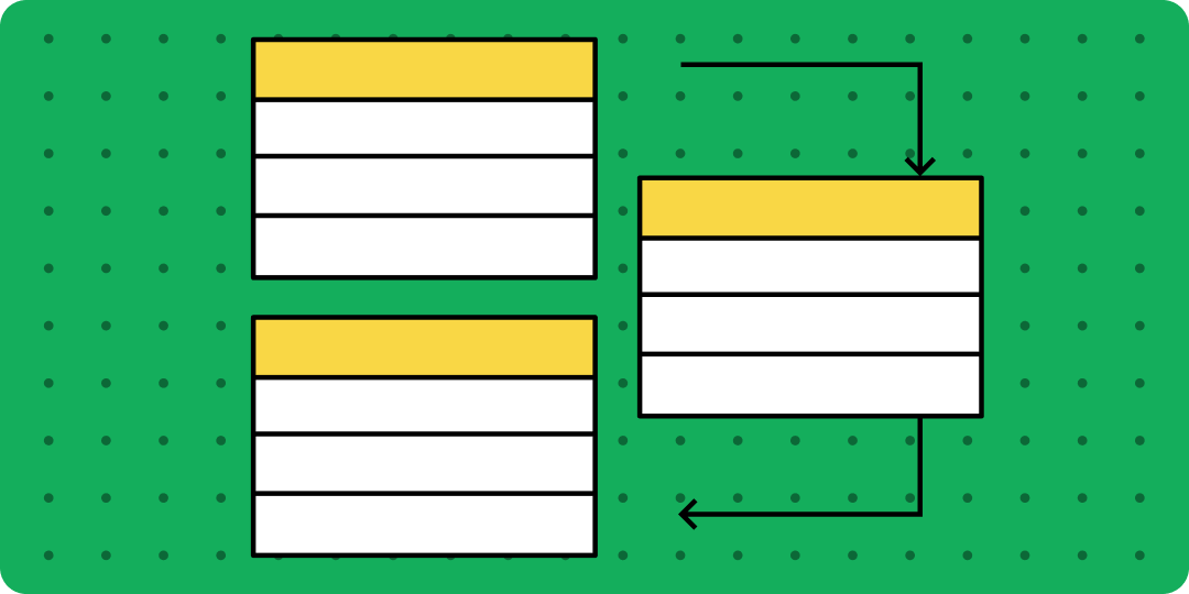
You've got a great idea for a new app or software feature—but first, you need to show your boss or investors what you have in mind. With a unified modeling language (UML) diagram, you can map out complex systems in a visual shorthand that’s easy to follow. UML diagrams give you a framework to document technical details, from object-oriented software to process workflows—and make them easy to understand, even for non-technical audiences.
Read on to learn more about:
- What a UML diagram is and why you should use one
- Different types of UML diagrams and how to read them
- How FigJam can help you simplify UML diagramming
A UML diagram serves as a blueprint for a software system and shows how it behaves. To standardize software modeling, UML diagrams use unified modeling language 1 . This helps developers and other key players describe, design, and document technical details with ease.
Why use a UML diagram?
UML diagrams can capture a wide variety of systems, from inventory systems to banking applications. UML diagrams are key communication tools to help you:
- Simplify large or complex systems. Technical and non-technical stakeholders can quickly grasp a product concept or app in development.
- Improve collaboration . UML gives developers with different language skills and processes a common language, so they can work better together.
- Drive alignment. Multiple teams can sync up with easy-to-understand diagrams.
- Show the complete picture . UML diagrams capture a system’s overall concept, key components, and functionality.
- Minimize errors . Teams can spot and resolve potential bugs quickly.
Create your UML diagram in FigJam
Build your blueprint and collaborate with your team for free in FigJam.
Types of UML diagrams—and how to read them
UML diagrams come in 14 flavors that fall within two basic categories: structural and behavioral. Once you understand how these diagrams work, you'll be able to read and build any UML diagram.
Structural UML diagrams
Structural diagrams represent technical frameworks, detailing static components in a structure or system.
UML class diagrams
These diagrams capture classes (or objects), showing their attributes, methods, and relationships. For example, in a login system, user information, role, permission, and password could each represent a class, with arrows showing relationships among them. User information attributes might include username, email, and password. Methods or functions could include add username, edit username, and delete username.
UML component diagrams
Organize components and subcomponents in an object-oriented system, and record how these components interface with each other. In an email app, components might include email management, inbox, and outbox. Subcomponents of email management could include system administration and front-end HTML.
UML composite structure diagrams
Use these diagrams to show how the parts of a system connect to make a system run. For a bank ATM system, those parts might include a central processor, card reader, memory, and modem.
UML deployment diagrams
This is how you demonstrate software deployment across hardware components. Your deployment diagram could show hardware such as a client server, database server, and an individual PC, with collaboration software layered on top of it.
UML object diagrams
These models capture object-oriented systems, just like class diagrams do. However, object diagrams depict a system at a specific time—useful for testing different class diagram instances.
UML package diagrams
Group high-level system elements into (yep) packages, or folders, to show their hierarchy, relationships, and dependencies. Use these diagrams for medium- to large-scale layered apps, such as an omnichannel shopping platform.
UML profile diagrams
Extend your UML models by adding tags, stereotypes, and constraints. This lets you customize diagrams for a specific industry (say, telecom or retail) or platform (such as J2EE, Java, or .NET).
Behavior UML diagrams
Behavioral diagrams model interactions in a system’s dynamic sequence or flow.
UML activity diagrams
Similar to flow charts , these diagrams plot out a system’s business or process flows—for example, payment, registration, and travel booking flows.
UML communication diagrams
Use these diagrams to illustrate how objects send and receive messages. For example, a travel reservation system might show a flight booking message passed from object to object. Those objects could include the front end, flight carrier, reservation, and confirmation.
UML interaction overview diagrams
Highlight the activity and sequence between interactions. For example, an online shopping system could include searching, browsing, shopping, and checking out. An interaction overview diagram can account for the path customers take through all these processes.
UML sequence diagrams
This is how you show the sequence of interactions between objects. These diagrams depict how an actor or user interacts with a system, and how the system responds.
UML state machine diagrams
Capture a system’s components in various states, as they respond to external and internal influences. For example, a debit card inserted into an ATM might result in a ready state or a failure state. Your state machine diagram might show both states, along with other possible states.
UML timing diagrams
Focus on the timing of events that affect system interactions. For example, your timing diagram for web browsing might display various states—waiting, processing, idling—and how long each state takes when a user browses a website.
UML use case diagrams
Identify the actors that use a system, and show how they interact with it. For example, an online ordering system might engage new and existing customers, a procurement manager, customer service agent, and AI chatbot. Use case diagrams also look at internal and external factors that influence functionality.
Understanding UML Relationships
On UML diagrams, you'll notice that UML relationships fall into four basic categories 2 :
Association: Usually this is a unidirectional or bidirectional link between objects—for example, an employer-employee relationship. Associations can also capture one-to-one, one-to-many, many-to-one, or many-to-many relationships.
Dependency: When one component depends on another, that's a dependency. For example, a change in supply could affect the client in a supplier-client relationship.
Generalization: Generalizations help define the connection between a general and specific object—for example, the relationship between a bank account and a checking account.
Realization: Realizations occur when one component (e.g., the client) realizes or implements the behavior defined by another component (e.g., the supplier).
Simplify UML diagramming with FigJam
Now that you’ve learned how to read UML diagrams, you can build your own. Capturing systems doesn't have to be difficult. Use FigJam’s UML diagram tool to:
- Plot out your UML diagram with FigJam’s ready-made shapes, tabbed folders, lines, and text tool.
- Lead an open session to collaborate and gather team feedback.
- Create presentation-ready models using components and styles from your Figma design library.
For design inspiration, check out UML diagrams shared by the Figma community —including Saki Takamachi’s popular UML class diagram .
Ready to capture technical concepts and win approval for your innovation?
Go to next section
[1] https://www.omg.org/spec/UML/2.5.1/PDF
[2] https://www.tutorialspoint.com/uml/uml_building_blocks.htm
Keep reading
How to create a flow chart
Having a flow chart can help visually represent actions or people in a complex situation.
What is sprint planning
Find out how to plan sprints effectively with a step-by-step guide, pro tips, and tricks from FigJam

What is a fishbone diagram
Use a fishbone diagram to help you solve problems by understanding what’s causing them.

UML Diagram Types Guide: Learn About All Types of UML Diagrams with Examples
Updated on: 28 September 2022
UML stands for U nified M odeling L anguage. It’s a rich language to model software solutions, application structures, system behavior and business processes . There are 14 UML diagram types to help you model these behaviors.
You can draw UML diagrams online using our software, or check out some UML diagram examples at our diagramming community.
List of UML Diagram Types
So what are the different UML diagram types? There are two main categories; structure diagrams and behavioral diagrams . Click on the links to learn more about a specific diagram type.
Class Diagram
Component diagram, deployment diagram, object diagram, package diagram, profile diagram, composite structure diagram, use case diagram, activity diagram, state machine diagram, sequence diagram, communication diagram, interaction overview diagram, timing diagram.

Structure diagrams show the things in the modeled system. In a more technical term, they show different objects in a system. Behavioral diagrams show what should happen in a system. They describe how the objects interact with each other to create a functioning system.

Get More UML Class Diagram Examples >>
A component diagram displays the structural relationship of components of a software system. These are mostly used when working with complex systems with many components. Components communicate with each other using interfaces . The interfaces are linked using connectors. The image below shows a component diagram.
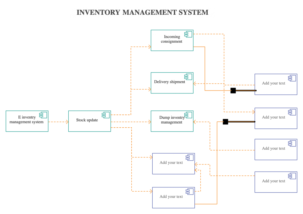
Get More Component Diagram Templates >>
A deployment diagram shows the hardware of your system and the software in that hardware. Deployment diagrams are useful when your software solution is deployed across multiple machines with each having a unique configuration. Below is an example deployment diagram.
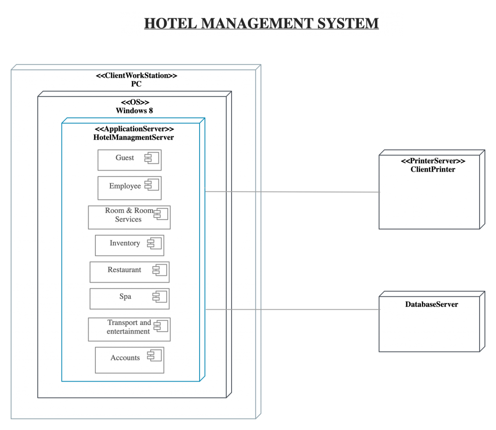
Get More Deployment Diagram Templates >>
Object Diagrams , sometimes referred to as Instance diagrams are very similar to class diagrams . Like class diagrams, they also show the relationship between objects but they use real-world examples.
They show what a system will look like at a given time. Because there is data available in the objects, they are used to explain complex relationships between objects.
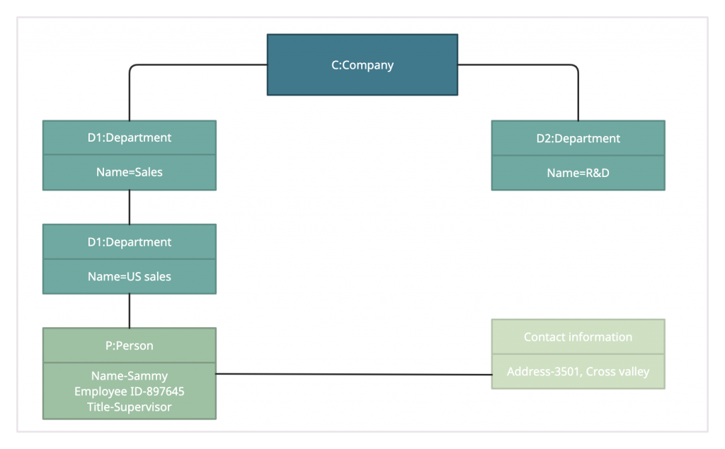
Get More Object Diagram Templates >>
As the name suggests, a package diagram shows the dependencies between different packages in a system. Check out this wiki article to learn more about the dependencies and elements found in package diagrams.

Profile diagram is a new diagram type introduced in UML 2. This is a diagram type that is very rarely used in any specification. For more profile diagram templates, visit our diagram community .

Composite structure diagrams are used to show the internal structure of a class. Some of the common composite structure diagrams .

As the most known diagram type of the behavioral UML types, Use case diagrams give a graphic overview of the actors involved in a system, different functions needed by those actors and how these different functions interact.
It’s a great starting point for any project discussion because you can easily identify the main actors involved and the main processes of the system. You can create use case diagrams using our tool and/or get started instantly using our use case templates .
Use Case Diagram Relationships Explained with examples
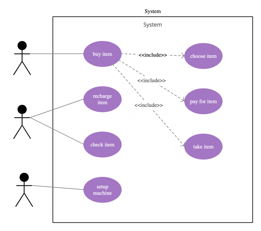
Get More Use Case Diagram Examples >>
Activity diagrams represent workflows in a graphical way. They can be used to describe the business workflow or the operational workflow of any component in a system. Sometimes activity diagrams are used as an alternative to State machine diagrams. Check out this wiki article to learn about symbols and usage of activity diagrams. You can also refer this easy guide to activity diagrams.
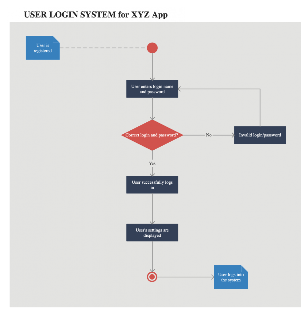
Get More Activity Diagram Templates >>
State machine diagrams are similar to activity diagrams, although notations and usage change a bit. They are sometimes known as state diagrams or state chart diagrams as well. These are very useful to describe the behavior of objects that act differently according to the state they are in at the moment. The State machine diagram below shows the basic states and actions.

Get More State Chart Diagram Examples >>
Sequence diagrams in UML show how objects interact with each other and the order those interactions occur. It’s important to note that they show the interactions for a particular scenario. The processes are represented vertically and interactions are shown as arrows. This article explains the purpose and the basics of Sequence diagrams . Also, check out this complete Sequence Diagram Tutorial to learn more about sequence diagrams.
You can also instantly start drawing using our sequence diagram templates .
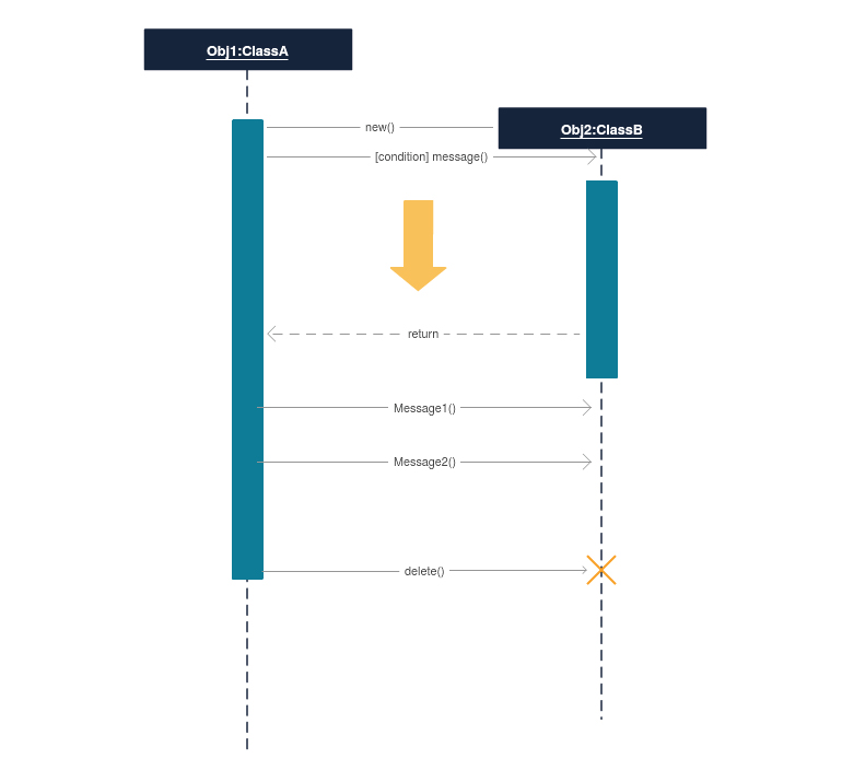
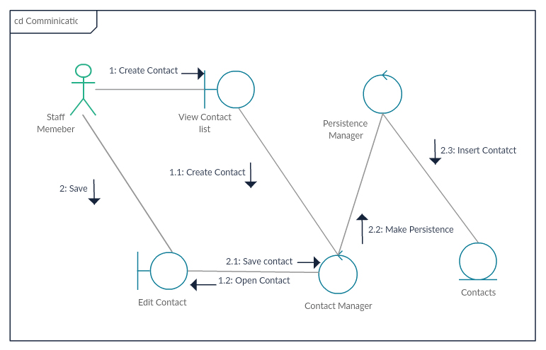
In UML 1 they were called collaboration diagrams . Communication diagrams are similar to sequence diagrams, but the focus is on messages passed between objects. The same information can be represented using a sequence diagram and different objects. Click here to understand the differences using an example .
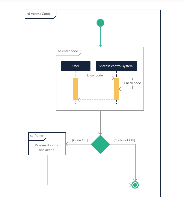
Interaction overview diagrams are very similar to activity diagrams. While activity diagrams show a sequence of processes, Interaction overview diagrams show a sequence of interaction diagrams.
They are a collection of interaction diagrams and the order they happen. As mentioned before, there are seven types of interaction diagrams, so any one of them can be a node in an interaction overview diagram .
Timing diagrams are very similar to sequence diagrams. They represent the behavior of objects in a given time frame. If it’s only one object, the diagram is straightforward. But, if there is more than one object is involved, a Timing diagram is used to show interactions between objects during that time frame.
Click here to create your timing diagram .

Mentioned above are all the UML diagram types. UML offers many diagram types , and sometimes two diagrams can explain the same thing using different notations.
Check out this blog post to learn which UML diagram best suits you . If you have any questions or suggestions, feel free to leave a comment.
Join over thousands of organizations that use Creately to brainstorm, plan, analyze, and execute their projects successfully.

More Related Articles
This is amazingly helpful. I’ve been trying to read and learn enough about UML to use it for some complex areas in some software I’m developing and have found it hard to grasp quickly, until I found this page. Thank you for taking the time to do it!
plz send me uml diagram for online bus reservation system
Hi Priya, check our community for various UML diagram types examples. Here’s the link https://creately.com/diagram-community/popular
Is there a UML model that exemplifies a nightclub system?
it is very nice but there is no clear idea in database design and physical design
aspect where models are used. can someone answer
Information is brief and helpful for basic knowledge of UML diagrams. Thank you.
First comment was in 2012. Ahh, where’re I at that time … Thank you! It’s very useful and easy to study. If I find this earlier … Thanks you!
Wow it is very use full and easy to study… ???
Thnkq lot…
which UML version does this tool currently support?
Hi Janie, We currently support most of the features in UML 2. Is there any specific feature that you require ?
I need help in sequence diagram for smart city app..can anyone help me
I need chart which summarizes the history of the evolution of UML until 2016?
Valuable discussion ! I loved the information . Does someone know if my business can get ahold of a sample AZ SOS Recall Petition document to fill in ?
it help to easy to study it………….. thanqqqqqqqqq. …………..
thank you very much, before midterm its like heaven
Any idea how a MF/legacy system will use UML diagrams…or what is the best way to use some of these diagrams for this environment.
simple and clear, thanks.
So educative, more grease to your elbow.
it help to easy to study it
This this very supportive for me. I just wa to know is there a way to see the UML diagram from multiple python source files. We have a hierarchy of classes spread in a package. How can I see the diagram for entire package?
It’s very help the learner, thank u much.
Hurrah! After all I got a webpage from where I can really get useful facts regarding my study and knowledge.
Brilliant article!
Thanks a lot! Very easy to understand!
Keep it going on mate!
Nice article. Only if there was use for all of these in real software projects. Seriously, who is using all of these, NASA? In reality maybe sequence and class diagrams are used (at most).
help in studt thanks
a good article. was very helpful thanks
very easy to understand thanks
thank you very much brother hope through hard work every thing is possible
helpful in did, thank you.
wow !!!!!!!!! ITS TOOO GOOOOOOOOOOOOOOOODDDDDDDD……………
very useful article … thanks for sharing
There’s an error here: “In large systems with many classes related classes are grouped together to to create class diagrams.”
Thanks for the article.
Hi Francesco, can you please explain the error there? A class diagram is a collection of classes so I feel the sentence is correct. Do think its confusing or misleading? Thanks for the feedback.
Maybe it’s just confusing because you’re not using any punctuation. Please correct me if I’m wrong but I guess this is what you wanted to say: “In large systems with many classes related, (comma) classes are grouped together to (the second “to” here should be removed) create class diagrams.”
Hi Francesco, agree that it is misleading and confusing. Thanks for pointing it out and I have modified the article. Hope you enjoyed the article.
Yes I did, it’s definitely useful 🙂
This is a very helpful and compact article. Thank you boss..:)
Thanks a lot dear! Much Appreciated!
This is really a splendid job
I am an Engineering Student This Arun Kumar Notes U have Gives is very informative Sir…
hi, this is wonderful job keep up.
Hi Nishada, what a very helpful note you have given! I have a question. Pls can UML diagrams be used for the understanding of problem domain? if yes, please explain. Thanks. Kind regards
This is really an awesome article.. thanks buddy
Quite useful even if we don’t need all schemas
Very nice and clean explanation. UML made easy! Thank you.
tomorrow is my exam .. n it helps me a lot ..stay blessed 🙂
it’s very useful for me, Thanks a lot
Hi very help in business plan and safe time.
Thank you. Nice Article.
Hi Nishadha ,Have seen many UML diagram before, however, the way to put it all together and characterize them is very important as the author has done it here. Very nice way to represent and identify them.thanks very thanks…of iran kelardasht good time
its very useful….without book we easily got …idea
i love your piece on UML, hope it help me with my exams tomorrow. Really appreciate your generousity
Have seen many UML diagram before, however, the way to put it all together and characterize them is very important as the author has done it here. Very nice way to represent and identify them. Enjoyed it…
much impressive task for learning
This site is very helpful! 🙂 🙂 🙂 Thank You very much!!!!!
hi man, very nice job. thx a lot~
Very helpful for beginners and easy to include in interview facing process.
this very useful for the understanding the uml concept
Most Effective notes
many types of UML diagrams information contained highly detailed easy to understand
very helpful, u made my day!!!
Great stuff,Thanks a lot.
thksss a lottt
That was pretty informative stuff, and you sire explained it pretty easily!
Receive your great thanks.This is great work ,thank you!!! continue posting others articles like this.
YOUR CUSTOMER
thanks this article is very helpful and easy to understand…great work
Hi Fabio, As I have listed down in the article, there are 14 UML diagram types in UML 2.0
Hi Nishadha , I find this very helpful and easy to understand, but I have a question about the number of Diagram, I read this http:/www.omg.org/gettingstarted/what_is_uml.htm and I found ” ..representing the results using UML 2.0’s thirteen standard diagram types.” 13 or 14 ?
Simple and easy to understand
superb.this page is eye catching.kudos quality stuff
what would you suggest if you want to build a diagram in which would be displyed a student grades; minimum grades to to pass a exam; final result pass or fail
Great explanation! My compliments. Simple and expressive.
thank u very much 4 ur article… its very helpful
Its very helpful site
its very helpful uml diagram
thank u lots…its v helpful to understand:-)
really helpful… thank yu so much :):) 🙂 🙂
thanks very helpful
Thank you so much…. 😀
Hello Nishadha, Thank you for the very nice article.
Cheers!! PP
hi nishadha, its very useful and very easy for understanding.. Thanks
Hi Varun, I haven’t used MATLAB so not sure what exactly you mean by develop logic using UML. Can you explains it a bit further ?
Hello Nishadha, Thank you for the very nice article. I have a question, is it possible in any way that we can develop logic using UML for example we can develop a logic using MATLAB.
nice one…really useful
its really helpful … thanks
Good morning, Clark. I apologize for the mistakes. Thanks for taking the time to point them out. I have corrected them now. Enjoy the article and hope you got some value from it.
By using 1 case study if you make these 14 diagrams then it will very helpful now it is although good but if you do like i say you then it much be better …! nice work
Good morning, Nishadha. I like the presentation of this information since it provides brief explanations and examples and links to greater detail.
I did notice that a few of your shortcut links up top are broken. Near the very beginning of your UML diagram types page you provide a numbered list of diagram types. Each link is supposed to take me to the brief explanation and example, but numbers 7, 10, and 14 don’t work. Number 13 actually takes me to the location for number 14.
Overall, this is a convenient presentation. Thanks.
super and easy to understand
super,its easy to understand for student
it is good to see
thankzzzz…vry informative and quick to learn!!!!
very good explained
like the way u in 🙂
Thank you for the clear diagrams and explanations.
very well explained
it’s simple and understandable
it’s easy to understand
Thankz its usefull 4 my studies.. thankz u….
its very helpful to me……….
simple and helpfull………Thanks a lot.
Looking for such documents for a long. Will also help me to conduct the training programs as well.
Thanks a lot.
very helpful …
It’s easy to understand… Thanks a lot…
very helpful n eseasy to underatand
This is a very helpful overview with manyuseful links. Thanks alot for your effort.
[…] The Completed Guide with UML Diagrams and examples by Creately (flowcharts, wireframes, UML, mindmaps, and more) […]
its really helping us to provide a lot of info we are gaining from it….
very helpful to me, thankzzzzzzzz
Good job I like it….
very helpful…………could have been better for beginners if each symbols were explained first….
its very helpful n easy 2 understand,thanx a lot…………
[…] particular system using the conventions set by the Unified Modeling Language (UML). Out of all the UML diagram types it is one of the most used ones. System designers use class diagrams as a way of simplifying how […]
Very Helpful Thanks……
Leave a comment Cancel reply
Please enter an answer in digits: 3 × 2 =
Download our all-new eBook for tips on 50 powerful Business Diagrams for Strategic Planning.

UML Tutorial – Learn Unified Modelling Language Diagram
UML Tutorial Summary
This Online UML Course is a step by step guide to learn UML. This free UML tutorial covers topics like Use Cases, Object Diagrams, Component Diagrams, State Diagrams, Activity Diagrams, etc.
Prerequisites of Learning UML Tutorial
This online UML guide is designed for beginners with no knowledge of UML.
UML Diagram Tutorial Syllabus
Introduction, advanced stuff, what you will learn in this uml diagram tutorial.
In this free UML tutorial for beginners, you will learn about Introduction to UML Diagrams, UML Notations, Relationships, Class Diagrams, Object Diagrams, Use Case Diagrams, State Machine Diagrams, Component Diagrams, Deployment Diagrams, and UML Tools.
What is UML?
UML stands for Unified Modeling Language. It is a standard which is mainly used for creating object-oriented, meaningful documentation models for any software system present in the real world. It provides us a way to develop rich models that describe the working of any software/hardware systems.
What is UML Diagram?
UML Diagrams are the output of the Unified Modeling Language. It is a pictorial representation of classes, objects, and relationships between them. UML diagram is a model that describes a part of a system. It is used to define the functionality or a design of a system. A diagram must be clear and concise so that the viewer will readily understand it.
Types of UML Diagrams
Here are the main types of of UML Diagrams:
- Structural Diagram:
- Class diagram
- Object diagram
- Package diagram
- Component diagram
- Deployment diagram
- Behavioral Diagram:
- Activity diagram
- Use case diagram
- State machine diagram
- Interaction Diagram:
- Timing diagram
- Sequence diagram
- Collaboration diagram
What are UML diagrams, and how can you use them?
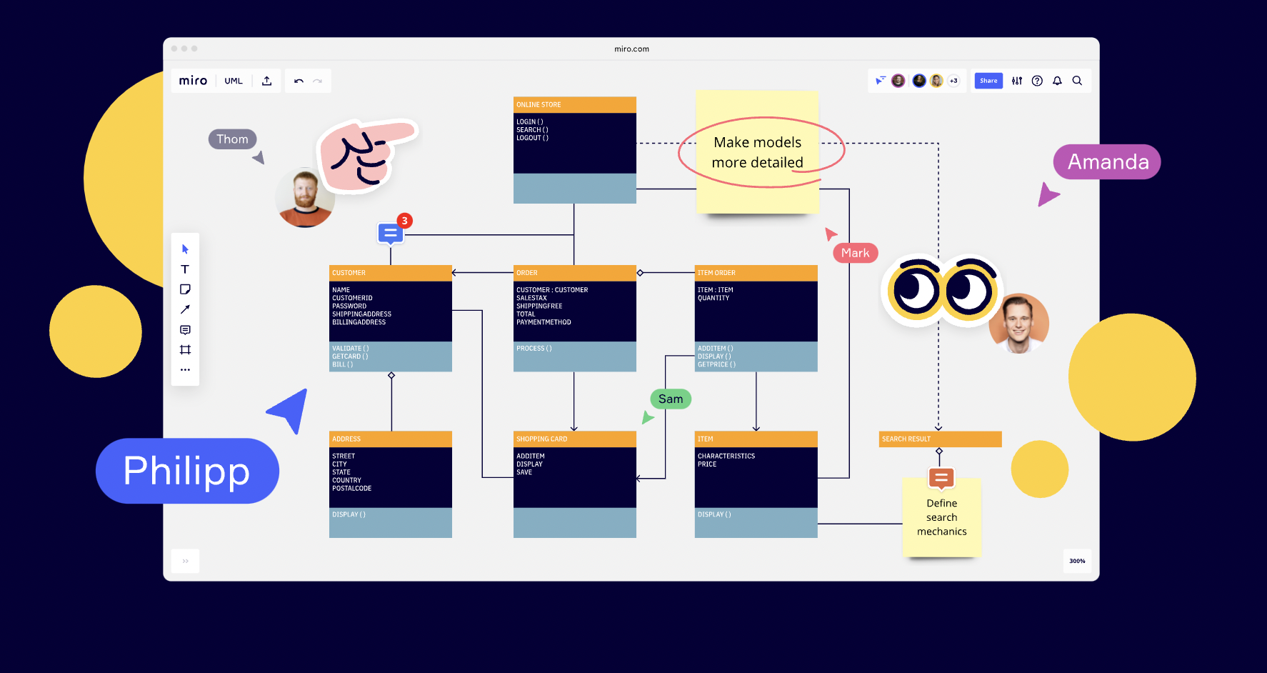
If you have a background in coding, you’ll probably be familiar with UML diagrams. Why? Because typically, software developers use UML diagrams to create new systems. But in today’s world, they’re not limited to a single capacity. In fact, UML diagrams are used widely across different areas of business.
So whether you’re a business manager or a software developer, an understanding of UML diagrams can go a long way. It’s always helpful to refresh your memory and familiarize yourself with the best practices for UML diagramming.
In this article, we’ll outline what UML is, how to use a UML diagram, and the different types of UML diagrams out there.
Why was UML developed?
Unified Modeling Language (UML) is a standardized modeling language. It helps software developers visualize, construct, and document new software systems and blueprints.
UML is used to create static structure diagrams based on a variety of engineering practices that have proven to be successful in the creation of complex systems. The published standards are almost 800 pages long.
Historically, UML has been used to model software systems, but it’s not limited to software developers. Today, UML diagrams are also used to manage processes and projects. In this scenario, UML diagrams outline entire workflows and business processes.
UML was created in 1995 by Grady Booch, Ivar Jacobson, and James Rumbaugh. In 1997, the Object Management Group adopted UML, meaning it was rolled out to companies such as Hewlett-Packard, Apple, and IBM.
In 2005, the International Organization for Standardization (ISO) standardized it. It’s constantly been reviewed and revised since then, with the latest UML specification taking place in 2015.

UML was created as a clear modeling language for developers to use. It was designed to be simple and easy to understand so that everyone could follow the process and design of the software.
Today, it’s not just used by software developers. It’s a more widely used approach to application structures and modeling, as well as documenting software.
What is a UML diagram?
For software developers, keeping on top of hierarchies and relationships within a system can be difficult — especially when focusing on complex and detailed areas of code.
But using a UML model divides these systems into components and subcomponents. This makes it easier to visualize, plan, and execute their project.
For business analysts, a UML diagram helps them visualize the system or process they’re working on.
When it comes to creating a UML diagram, a lot of businesses use a UML diagram template .

Using a ready-made template saves time and allows you to create a UML diagram as quickly and efficiently as possible.
When should you use a UML diagram?
Most commonly, a UML diagram is used to analyze existing software, model new software, and plan software development and prioritization. Simply put, if you need a way to visualize and plan your software development process, a UML diagram is incredibly helpful.
For business management, a UML diagram helps teams organize their workplace, create process documentation, and streamline their workflow.
They can also be used to update stakeholders on business operations and progress. And if you’re using a collaborative platform, you can easily invite external collaborators and stakeholders to view the diagram.
The benefits of using a UML diagram
Now that we know what a UML diagram is and what it’s used for, let’s take a look at some of the benefits of using it.
Keep everyone on the same page
UML is a standardized language. Every UML element means the same thing no matter what business is using them and what the diagram is for.
For example, the ‘actor’ icon represents a user. This could be a customer, someone on the internal team, or another system that interacts with the subject of the diagram (in this case, it would be your software).
This icon is always presented as a stick figure. Whenever anyone sees this icon, they’ll automatically know what it means in the context of your diagram.

So when it comes to creating a UML diagram, the standardized symbols make it easier for everyone to understand the diagram. There’s no confusion about what certain icons mean, and everyone knows how to read a UML diagram effectively.
Explore different options
Rolling out new software or updating an existing one can be a costly and time-consuming process. For this reason, it’s not always possible to test different versions of the software to see what works best.
This is where a UML diagram can help.
Before you launch the new software, you can use the diagram to test out different structures. As a result, you can make changes and improvements before launching the software. This saves you both time and money in the long run.
Have clear documentation of workflow
By using a UML diagram, you’re able to document your new software or business processes. This means you can track progress over time, make sure things are going to plan, and identify key areas of improvement.
Let’s say you’ve used a UML diagram to plan a new business process. The process has been rolled out to your team, and they’re following the new steps.
But something isn’t quite right. The process isn’t moving your workflow along as quickly as you’d hoped. To identify what’s causing the holdup, you refer back to your UML diagram and pinpoint the root of the problem. And once you’ve found the issue, you can put things right.
Most commonly used UML diagrams
There are various types of UML diagrams that are used for different software structures. There are 14 official types, with some additional versions that aren’t officially recognized but are widely used.
The diagrams are split into two different categories: structural diagrams and behavioral diagrams.
A structure diagram shows how a system is constructed. This includes components, classes, objects, and how all of these elements connect. Behavior diagrams visualize how a system interacts with itself, users, and other systems.
Here’s a breakdown of the different types of UML diagrams and whether they’re classified as a structural diagram or behavioral diagram:
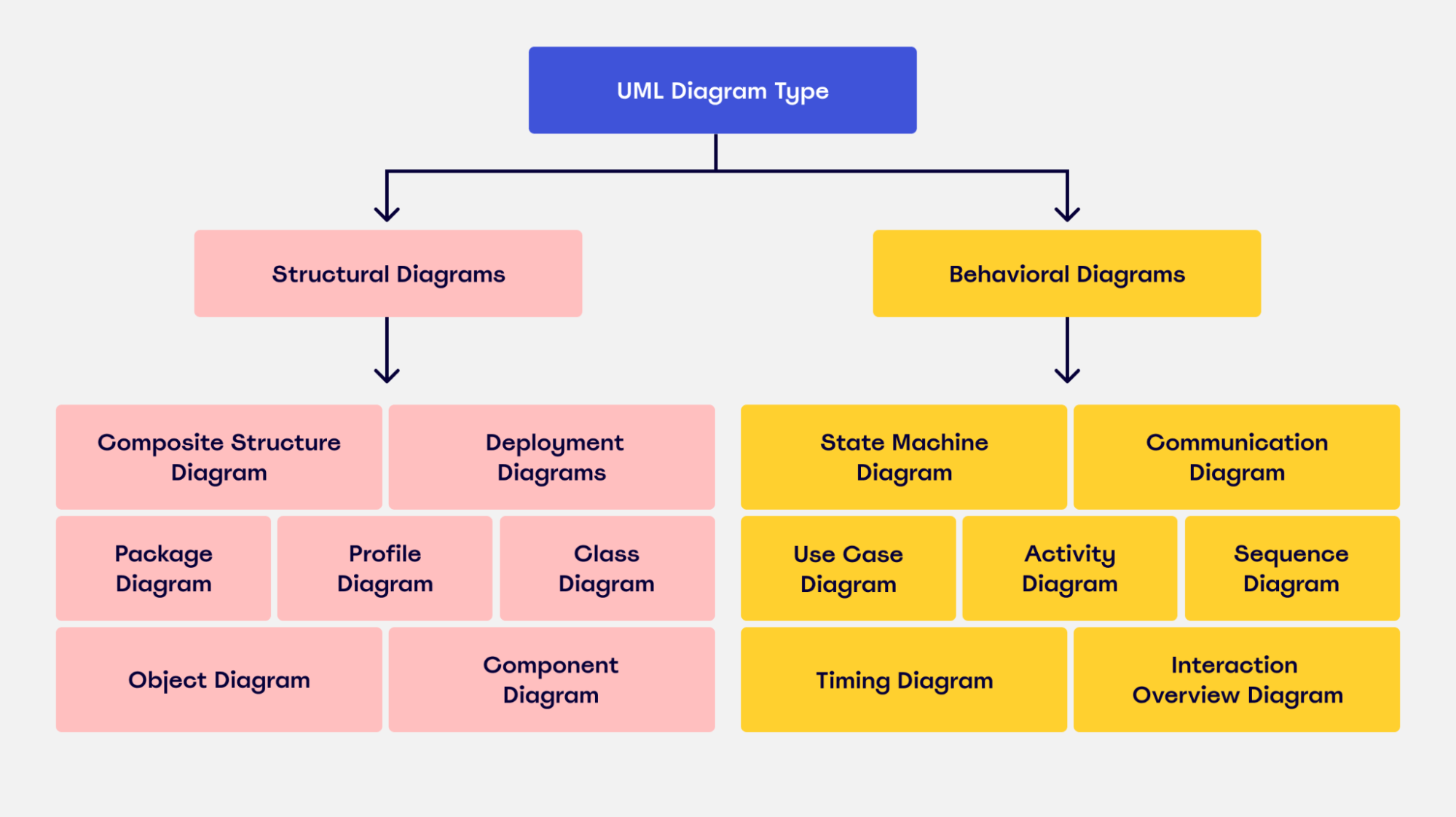
Now, let’s take a look at some of the most commonly used UML diagrams in more detail.
Class diagram
A class diagram allows you to map the structures of a system displaying various classes, attributes, operations, and relationships between objects. Both software engineers and business managers use this interaction diagram to model different connections involved within a process.
In the diagram, the class is represented with a rectangle. Each rectangle is split vertically into three sections. The top section has the name of the class. The second and third sections provide details about class operations, behaviors, and attributes.
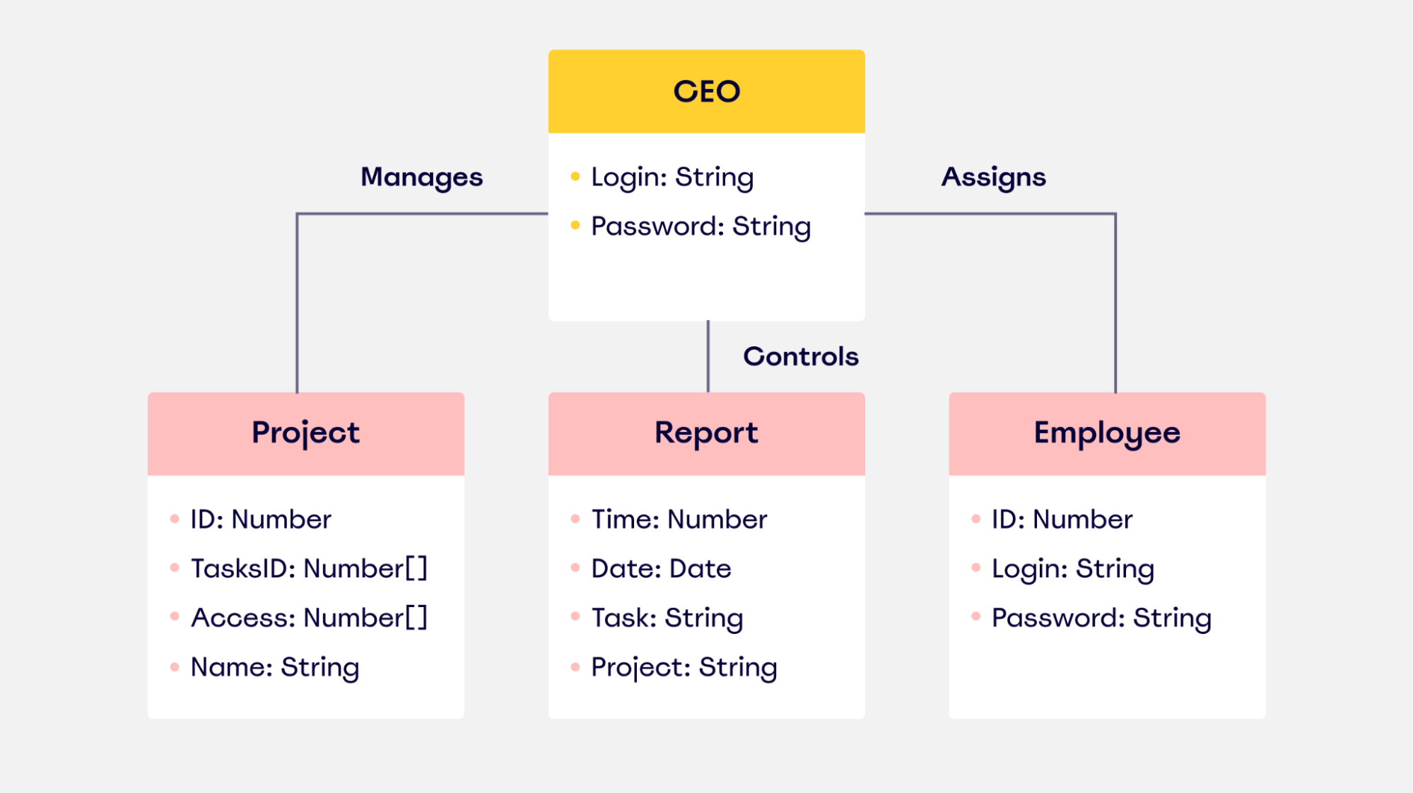
Because software is typically based on object-specific programming, a class diagram is probably the most commonly-used UML diagram.
Component diagram
A component diagram breaks down a complex system into smaller components, making it easier to visualize. Unlike other UML diagrams, it specifically outlines the relationship between these components.
Take a look at this example of a component diagram for a library management system:

You can see from the diagram that the main focus lies with how and where the different objects are connected.
Visually speaking, it’s pretty similar to a class diagram. It has the same notation rules, but it’s more specialized and tailored to a complex system.
Use case diagram
Use case diagrams show interactions between users — also known as ‘actors’ and represented as stick figures — and the system itself.
It illustrates system functionality, focusing on the expected behavior of the system and showing what will happen and when.

A use case diagram is often used as a top-level overview of how users and systems interact. As a result, it’s a useful way for a non-technical audience — which can include key stakeholders — to visualize your system.
Activity diagram
An activity diagram is a flowchart that outlines all the activities performed by a system.
It shows everything from start to finish, defining the various decision paths and steps that need to happen to move from one activity to the next. The steps can be chronological, branched, or simultaneous.

This diagram is commonly used to manage the internal structure of business processes. It allows business analysts to effectively plot and manage various workflows in one location.
Deployment diagram
Deployment diagrams show the configuration of processing nodes, as well as all the components that live on them.
In other words, they show how software runs on components within a system. It helps users model the physical aspects of object-oriented software.
These diagrams are mostly used by system engineers. By using this diagram, they can keep track of their entire hardware mesh and prepare the system for launch without any issues. It also allows them to see performance, maintainability, and scalability.
Sequence diagram
Sequence diagrams — sometimes known as event diagrams — show the order in which your objects interact. This includes the lifelines of your objects, the processes that interact with your objects, and the messages exchanged between the objects to perform a function.
These diagrams are often used by developers and business professionals to understand how to structure a new system or improve an existing process.
Take a look at this example of a UML sequence diagram for an ATM machine:

As you can see from this image, the sequence diagram outlines all the steps that interact with the ATM machine and the user. It covers all the possible actions the user can take and shows how the ATM machine will respond in each situation.
Object diagram
Object diagrams show the attributes of each object in a system and how those objects relate to one another at a specific time.
Take a look at this example of an object diagram for the use of a bank account:

The diagram shows the current state and attributes of the objects (the bank accounts) at this particular stage. It shows what actions the user can perform and the class limitations they have in place.
Object diagrams like this are often used alongside class diagrams. Why? Because an object diagram tends to represent a certain part of a class diagram.
In this situation, a class diagram would illustrate the entire baking system. An object diagram will focus on the use of different objects throughout the system. This helps you verify the effectiveness of your class diagram.
Package diagram
As the name suggests, a package diagram is used to show the dependencies and relationships between packages in a system. A package refers to anything that organizes any model element. In the diagram itself, it’s presented as a file folder.
The package diagram allows the user to group items into folders. Items that can be grouped include classes, use cases, documents, diagrams, and even other packages. Once each item is allocated to a package, all of the packages are then arranged and ranked hierarchically in the diagram.
These diagrams are mostly used to visualize software systems because they easily portray the top-level structure.
Best practices for creating a UML diagram
Now that you know about the different types, you’re probably wondering how to make a UML diagram.
While the process of creating one differs greatly depending on your business needs, we’ll outline a couple of the best practices you can follow.
Choose the right UML diagram type
We already know there are multiple versions of UML diagrams. So before you do anything else, you need to know what type of UML diagram you need.
To figure out which diagram is right for you, here’s what you need to do:
- Understand the different types of diagrams: To know which of the structure diagrams is right for your requirements, you need to fully understand the different types. This article is a great starting point, but there are other diagrams we haven’t covered. There are 14 official diagrams. Do some more research to give yourself a thorough understanding of what UML diagrams are available.
- Identify why you’re creating the diagram in the first place: Do you know what you want to learn from your diagram? Or why you need one in the first place? Or who you’ll be sharing it with? All of these questions need to be answered before you start your diagram. Without this information, it’ll be hard to choose a diagram that’s best suited to your needs.
Find the right software
Once you’ve done some additional research and figured out which type of UML diagram is right for you, you now need to find the right UML tool to create it.
There’s a lot of software out there to choose from, which can be pretty overwhelming if you’re new to UML diagrams.
To make the search easier and help you find the right modeling tool, here are some of the features we’d suggest looking out for:
Collaboration Keep an eye out for platforms that have collaborative features, such as a chat function, shareable boards , and even shareable screens .
Collaborative features allow you to work together with team members in one location. This makes it easier for everyone in your team to work on the same UML diagram, provide feedback, and use the diagram when it’s been approved.
INTegrate with third-party platforms Are you already using external tools as part of your workflow? If the answer is ‘ yes, ’ you’ll need a UML platform that allows you to integrate with these tools.
Whether that’s Zoom , Slack , Microsoft Teams , or any other platform you’re using to manage your workflow, your UML platform needs to be able to integrate with them. If it doesn’t, your productivity could take a hit.
Customizations Being able to customize your UML diagram is a great feature to have. It allows you to have some flexibility in the structure and design of your UML diagram, meaning you can create UML diagrams according to your needs and audience.
So what features should you look out for?
In all honesty, it’s up to you. Customizable features could be anything from adding text and shapes to creating new tables and even designing custom templates . Just make sure that you know what features you need before you start looking, and you can keep an eye out for something that fits the bill.
Create a UML diagram today
By now, you’ve got a pretty solid understanding of how to create a UML diagram. You know what the benefits are, you’re familiar with some of the most popular types of UML diagrams, and you’re up to speed with some of the best practices for creating your own UML diagram.
It’s time to put your newfound knowledge into practice.
If you’re thinking about creating a UML diagram, take a look at Miro. Our UML diagram template is perfect for collaborative teams looking to create intuitive and user-friendly UML diagrams.
It’s easy to share your diagram with other users and external stakeholders, and you can even customize your diagram to meet your requirements. Not to mention, our platform has all the UML icons. To try Miro, all you have to do is sign up for free , choose a template , and you’re good to go.
Miro is your team's visual platform to connect, collaborate, and create — together.
Join millions of users that collaborate from all over the planet using Miro.
Keep reading
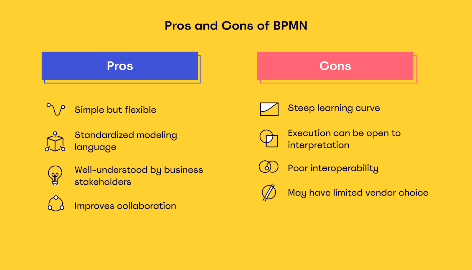
Business process modeling notation (bpmn): everything you need to know.
4 new features for diagramming

How to build a product roadmap that truly works (with Miro)
We use essential cookies to make Venngage work. By clicking “Accept All Cookies”, you agree to the storing of cookies on your device to enhance site navigation, analyze site usage, and assist in our marketing efforts.
Manage Cookies
Cookies and similar technologies collect certain information about how you’re using our website. Some of them are essential, and without them you wouldn’t be able to use Venngage. But others are optional, and you get to choose whether we use them or not.
Strictly Necessary Cookies
These cookies are always on, as they’re essential for making Venngage work, and making it safe. Without these cookies, services you’ve asked for can’t be provided.
Show cookie providers
- Google Login
Functionality Cookies
These cookies help us provide enhanced functionality and personalisation, and remember your settings. They may be set by us or by third party providers.
Performance Cookies
These cookies help us analyze how many people are using Venngage, where they come from and how they're using it. If you opt out of these cookies, we can’t get feedback to make Venngage better for you and all our users.
- Google Analytics
Targeting Cookies
These cookies are set by our advertising partners to track your activity and show you relevant Venngage ads on other sites as you browse the internet.
- Google Tag Manager
- Infographics
- Daily Infographics
- Graphic Design
- Graphs and Charts
- Data Visualization
- Human Resources
- Training and Development
- Beginner Guides
Blog Data Visualization
11 UML Diagram Examples: Class, Activity, and More
By Danesh Ramuthi , Nov 08, 2023

A UML diagram is the visual blueprint of software and business processes, using the Unified Modeling Language as its foundation. This diagram plays a pivotal role in object-oriented design, capturing the essence of both static structure and dynamic behavior within software systems.
UML encompasses various diagram examples, each tailored to illuminate unique facets of a system. From class and activity diagrams which spotlight class operations and the static relationship of one class, to sequence and state diagrams revealing the dynamic behavior of a system.
For professionals, especially software engineers and business analysts, mastering these diagrams is essential for a holistic understanding of the object-oriented paradigm.
If you are ready to create an UML diagram then consider using the Venngage UML Diagram Tool & Diagram Templates for a seamless experience and let your diagrams do the talking.
Click to jump ahead:
11 UML diagram examples
Types of uml diagrams.
- Wrapping Up
The Unified Modeling Language (UML) offers a comprehensive set of diagrams to represent and design complex systems. For those interested in understanding the depth and breadth of UML, I present a selection of diagram examples. These examples provide insights into best practices and the utility of UML in various scenarios.
Let’s get into it.
UML class diagram
Among the various UML diagram examples, the UML class diagram is paramount for those engaged in object-oriented design.

Serving as a static structure diagram, it emphasizes the foundational elements of an object-oriented system. UML class diagrams typically showcases:
- Relationships
While the focus is primarily on the static relationship, the essence of the UML class diagram lies in its ability to offer a bird’s eye view of the system’s architecture.

When you’re crafting an online shopping platform or a hotel management system, class diagrams distill the intricate network of objects and their interactions, proving essential for both software engineers and business analysts.

UML activity diagram
Shifting from the static nature of class diagrams, the UML activity diagram brings to the forefront the dynamic behavior of a system. Resonating with the essence of a flowchart, the activity diagram maps out the flow from one activity to the next, visualizing the sequence of operations and their conditions.
Characterized by rounded rectangles representing activities and arrows indicating the flow direction, this diagram shines in scenarios that require understanding procedural logic, decision-making sequences, or concurrent operations.

For example, in an online shopping process, the activity diagram can depict stages like ‘Select Product’, ‘Add to Cart’, ‘Checkout’, and ‘Payment’, illustrating the flow and possible decision points like ‘Apply Coupon’ or ‘Choose Shipping Option’.
The true strength of the activity diagram lies in its ability to represent parallel and concurrent activities. It’s not just about the linear flow; it’s about capturing the entirety of a process, be it the parallel tasks in a hotel management system or the interconnected processes of a domain model.

UML Use case diagram
UML use case diagrams define expected behavior, focusing on the ‘what’ rather than the ‘how’. While use cases describe the system’s desired functionality, their true power lies in providing both textual and graphical representations.

From the standpoint of the end user, use case modeling shines. It enables a design perspective that emphasizes user interactions with the system, ensuring a user-centric approach. However, while a use case diagram provides an overview of actors and their interactions with the system, it deliberately omits details:
- Simplicity in design: A use case diagram maintains a simplistic nature, summarizing relationships without delving into step-by-step procedures.
- Avoid overcomplication: With ideally fewer than 20 use cases, a cluttered diagram might indicate a deviation from the intended use of use case diagrams.
- Focus on externally observable behavior: This ensures a clear communication of system behavior in terms relatable to the user.

New to user experience design? Here are 10 use case diagram examples that might help you out.

UML sequence diagram
The UML Sequence Diagram shows the detailed steps of how things work together. Unlike other diagrams which might focus on static aspects, sequence diagrams delve deep into the ‘when’ aspect of interactions, illustrating the chronological flow of operations.

Characteristics of sequence diagrams:
- Time-centricity: The vertical axis of the diagram embodies time, providing a chronological representation of message exchanges.
- Scope of interaction: It captures interactions as they occur within collaborations, providing insights into both specific instances and generic cases. This could range from high-level system interactions to user-system exchanges.
- Systematic flow: Unlike the use case diagram, sequence diagrams map out the meticulous order of interactions, showcasing the sequence of events and their associated timelines.

UML state diagram
State diagrams, synonymous with state machines or state-chart diagrams, bring forth the dynamic behavior of a system as it transitions through various conditions or states over time. It focuses not on the entire system but on individual parts or components and their responses to specific time-bound stimuli.

Key Aspects of State Diagrams:
- Dynamic representation: State diagrams represent conditions of a system at specific moments in time, offering insights into possible transitions and the events triggering them.
- Targeted modeling: While every class might inherently possess a state, it’s not essential to model them all. State diagrams primarily target classes with multiple transitional states.
- Response to stimuli: State diagrams are instrumental in understanding how objects or classes react to both internal and external events.
For professionals focusing on the dynamic aspects of system design, understanding state transitions, and pinpointing the events responsible for state changes, the UML State diagram proves to be an invaluable tool.

In the preceding section, we introduced a few types of UML diagrams that provide insights into system design and behavior.
However, the Unified Modeling Language (UML) is vast, and there are numerous other diagram types that software engineers, business analysts, and system designers frequently employ.
In this section, we will look into several additional UML diagrams, offering a concise overview of their purpose and significance.
- Component diagram : This diagram showcases the structural relationships between a software system’s components. Ideal for navigating multifaceted systems, component diagrams highlight communication patterns using interfaces connected by connectors.
- Structural UML diagrams : As the name denotes, these diagrams show the architecture of the system—capturing classes, objects, packages, and more. It provides a roadmap of how various elements within the system are interconnected.
- Deployment diagram : A vital tool for system engineers, deployment diagrams illustrate how software components are deployed onto hardware components, illuminating factors like performance, scalability, and maintainability. This aids in tracking the system’s hardware configuration seamlessly.
- Composite structure diagram : Think of these as the architectural blueprints for the internal configuration of a classifier. They offer insights into how various hardware components are internally composed and interact through ports.
- Object diagrams : These diagrams provide a snapshot of data structures at a specific instance. They often complement class diagrams, either by verifying the class structure or presenting specific examples of model element interactions.
- Package diagram : Used to visualize the dependencies among different packages in a system, package diagrams group model elements like classes or use cases under the umbrella of packages, aiding in the organization of system elements.
- Profile diagram : A recent addition, profile diagrams are a niche yet essential tool for customizing UML models tailored for distinct domains and platforms.
- Timing diagram : As the name suggests, these diagrams are time-centric, portraying the interactions between objects over a set period. They are invaluable for pinpointing process durations and identifying potential bottlenecks.
- Interaction overview diagrams : Providing a macro view of control flow between nodes, this diagram encompasses various nodes like decision, merge, fork, and join nodes, portraying a holistic view of system interactions.
- Communication diagrams : Previously termed collaboration diagrams, these diagrams paint a picture of how objects collaborate within a system’s architectural design. They are especially beneficial for representing alternate scenarios within use cases where multiple object interactions come into play.
Wrapping up
In this article, I aimed to explore the various UML diagrams by providing succinct, clear examples of class, activity, sequence, state, and use case diagrams. Each one, an integral piece of the software and business process puzzle, offers insights into specific aspects of system design, behavior, and interaction.
The Unified Modeling Language is not just a medium for representation; it’s the lingua franca for software developers and system designers worldwide. It bridges the gap between conceptualization and realization, ensuring that ideas are not just envisioned but are also manifested with precision and clarity.
Our exploration into a few UML diagram examples shed light on the core diagrams like the UML class, activity, and sequence diagrams, amongst others. These diagrams, while varied in their approach and focus, converge on a singular objective – to encapsulate the essence of a system or process, making it both comprehensible and actionable.
Furthermore, our deep foray into the different types of UML diagrams served as a testament to UML’s versatility. From detailing structural relationships in component diagrams to illuminating software deployment on hardware components, each diagram type has a unique role to play in the grand tapestry of system design.
Whether you’re a seasoned developer or a business analyst at the onset of your UML journey, tools like the Venngage UML Diagram Tool & Diagram Templates can be instrumental.
They not only simplify the design process but also elevate it, ensuring that your UML diagrams are not just accurate but also aesthetically appealing.
What is UML | Unified Modeling Language
What is UML?
The origin and history of uml, object-oriented concepts used in uml, what is a uml diagram.
- UML vs ER Diagram
- Types of UML Diagrams
Free UML Diagram Templates
Key uml diagram symbols.
- How to Draw a Wiring Diagram?
How to Start a UML-Based Development Project?
How to create a uml diagram easily.
The Unified Modeling Language (UML) is a language used in the field of software engineering that represent the components of the Object-Oriented Programming concepts. It is the general way to define the whole software architecture or structure.
In Object-Oriented Programming, we solve and interact with complex algorithms by considering themselves as objects or entities. These objects can be anything. It can be the bank or a bank manager too. The object can be a vehicle, animal, machine, etc. The thing is how we interact and manipulate them that they can perform tasks and they should.
The tasks can be interacting with other objects, transferring data from one object to another, manipulating other objects, etc. The single software could have hundreds or even thousands of objects. So, UML provides us a way to represent and track those objects in a diagram to become a blueprint of our software architecture.
The concept of UML was first developed at Rational Software in the late 1900s between 1994 and 1995. In 1997, a significant thing recorded as the Object Management Group (OMG) adopted UML as a standard to meet before developing a new system. The purpose of UML these organizations set is.
- The UML will provide software developers a blueprint and other tools for analyzing and designing the software architecture. It will also model business and other similar processes.
- It would pave a meaningful way to exchange information about the model between different tools, and a contract on explanation would be made.
The UML is evolving ever since its concept was made. In 1996, UML Partners was organized by Rumbaugh, Jacobson, and Booch to complete the formalities and specifications of the Unified Modeling Language (UML), and finally, in 1997, they published the UML 1.0 draft. It contains some lackings, so different versions were made after this, like UML 1.2, 1.3, etc.
The current UML the world is using is UML 2.x. In 2005, the UML 1.5 was replaced by the UML 2.0, the more developed and advanced version of its predecessor. However, after this, many versions were released, like 2.1.1, and 2.1.2, etc. The current and more advanced version we are using is UML 2.5. It contains more features than the UMLs before.
Before understanding UML, you should know what Object-Oriented Programming and its concepts are. The six main concepts of Object-Oriented programming concepts are.
The classes are the data structures that contain the properties, attributes, constructors, or methods. Consider it as a container. The class is also called a blueprint.
The objects are the real-world entities that the programmers deal with to solve real-world problems. The object can be anything from a human to a building, etc.
Inheritance
Inheritance is the word that we all are familiar with it. Inheritance in OOPs makes you inherit a sub-class from the superclass. When you inherit a class from the superclass, you can access the superclass properties, constructors, methods, and objects besides the properties or methods private to the superclass.
Abstraction
Abstraction makes you hide the details of functionalities of a class from a user. In abstraction, you initialize methods in an abstract class and define those methods in the inherited sub-class.
Encapsulation
Encapsulation makes you provide security to your properties and methods from the outer world. You define encapsulation by making getter and setter methods.
Polymorphism
"Poly" means "many," and "mor" means "form or face." Binding together makes "many forms.” Polymorphism makes you make many attributes and methods from a single method or attribute in a class by method overloading and method overriding concept.
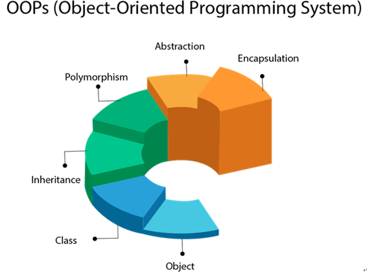
Source: francescolelli.info
A UML diagram shows the unified visual presentation of the UML (Unified Modeling Language) system intending to let developers or business owners understand, analyze, and undertake the structure and behaviors of their system.
So far, the UML diagram has become one of the most common business process modeling tools, which is also highly significant to the development of object-oriented software.
Why Use UML Diagrams?
UML diagrams have many benefits for both software developers and businesspeople, and the most key advantages are:
- Problem-Solving - Enterprises can improve their product quality and reduce cost especially for complex systems in large scale. Some other real-life problems including physical distribution or security can be solved;
- Improve Productivity - By using the UML diagram, everyone in the team is on the same page and lots of time are saved down the line;
- Easy to Understand - Since different roles are interested in different aspects of the system, the UML diagram offers non-professional developers, for example, stakeholders, designers, or business researchers, a clear and expressive presentation of requirements, functions and processes of their system.
Usages of UML Diagrams
The diagram can be used in many different fields including software engineering or business processes to strengthen efficiency.
- Draft the System - In this case, the UML diagram is used by the development team to discuss the outlines and structure the overall system. This may include the forward design and the backward design for different activities, roles, actors, and so on;
- Visualize Programming Language - Different types of UML diagrams in a certain system can be translated into code directly to save time for software or related application development;
- Business Analysis - In reality, the UML diagram can also be used to analyze the business sales pathway in order to improve customer service;
UML vs. ER Diagram
The main differences between the UML diagrams and ER diagrams are listed below.
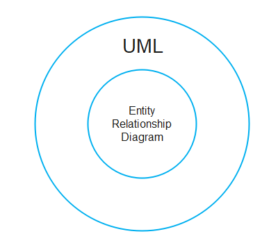
Types of UML Diagrams?
The two most main categories of UML diagrams are the Structure UML diagram and the Behavioral UML diagram . Furthermore, 14 sub-types of UML diagrams are divided into these two groups and each one of them has a different purpose. Now let's check out all of them in more details as shown below. You can also click on them to see more and download these examples for free.
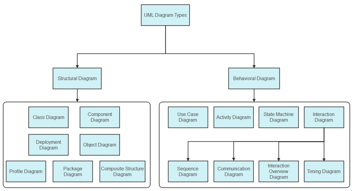
Structure Diagrams
These diagrams show different objects and the static structure of the system. The elements in a structure diagram may include abstract and some other related implementation concepts. This category has six sub-types:
- Class diagram
- Composite Structure diagram
- Object diagram
- Component diagram
- Deployment diagram
- Package diagram
Profile Diagram
Class diagram.
It is the most widely used UML diagram sub-category. The class diagram is the building block of all object-oriented software systems. Users can depict the static structure and identify classes relationship of a system by checking system's classes and attributes. Each class has three basic elements: the class name at the top, the class attributes in the middle, and the class behaviors at the bottom. In reality, you can create classes such as "Sales Account" or "Online User" in business systems, or "Teacher" and "Student" in academic systems.
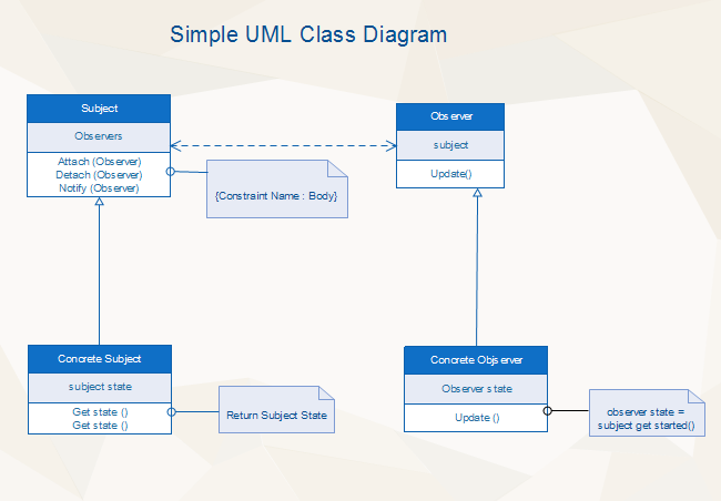
Composite Structure Diagram
Composite Structure Diagrams are used to show the internal structure, the behaviors of classifiers, and the relationships between classes in a system. The composite structure type is similar to Class diagrams but the former ones represent more detailed individual parts rather than the whole system structure.
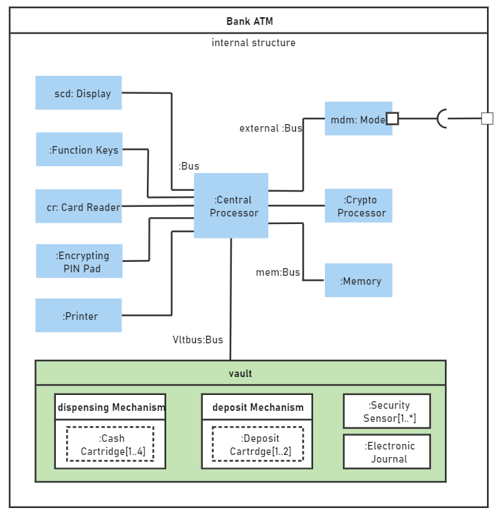
Object Diagram
Object Diagrams can be considered as the screenshot of the instances and their internal relationships in a specific system. By using such diagrams, developers can be able to analyze the operations of the system at a particular instant, and check their abstract structure. Furthermore, the relationship between a Class and an Object in software development can be described as the relationship between, for example, the class "Food" and the brand "KFC" or the general class "User" and a specific username called "David" or what else.
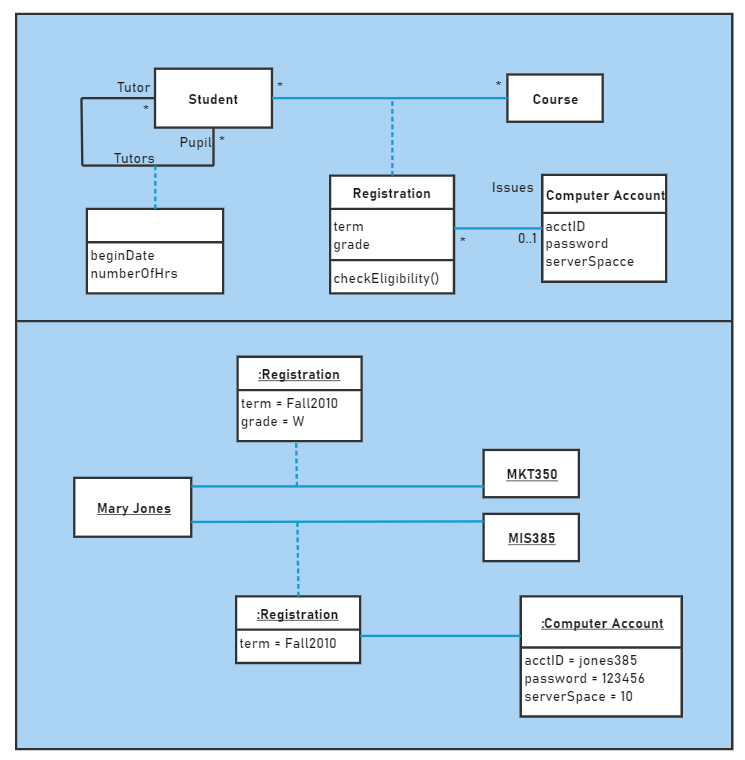
Component Diagram
Component Diagrams are used to show in what way the physical components in a system is organized. Normally, developers use the Component Diagram to check out implementation details, break down the system into smaller parts, depict the structural relationship between system elements especially in the case of large-scale complex projects with more advanced technologies.
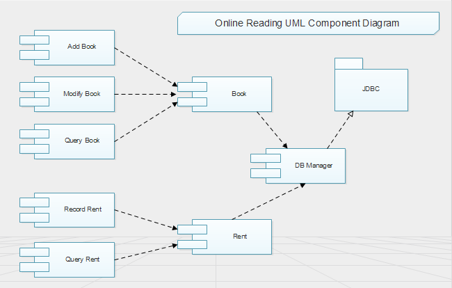
Deployment Diagram
Deployment Diagrams are generally used to show users the visual relationship between software and hardware. A sample Deployment diagram in the software development field has two main parts: Nodes (basically different kinds of servers) and Artifacts (normally client or database schema). Nodes host the Artifacts, while different types of Artifacts operate on Nodes.
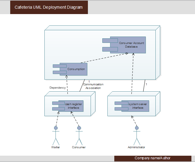
Package Diagram
In general, Package Diagrams are used to depict how packages and their elements are organized into meaningful groups in a system. More specifically, Package diagrams can be considered as a structure that includes many deployment diagrams with nodes and artifacts. So far, package diagrams are used to organize the Class and Use Case diagrams.
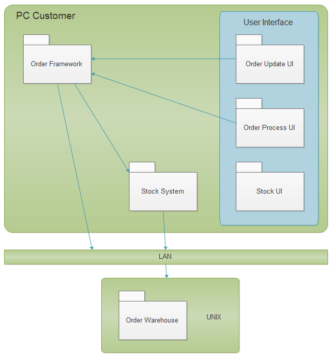
The profile diagrams are an extension of Unified Modelling Language (UML), which are a structural diagram that use stereotypes, tagged values and constraints to extend and customize UML.
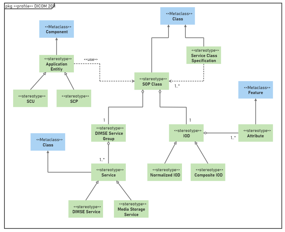
Object diagram vs. Class diagram
The object and class diagram share the same concept but yet they have a difference.
The class diagram is a diagram that represents the structure of classes in the software. This diagram represents what the class contains and how they are interacting with other classes in the software. The class diagram shows the relationship between different classes in the software architecture.
But, the object diagram shows the properties of objects, how they are interacting with other objects, how they're using different methods of classes to communicate with other objects of the class. The class diagram is all about classes, and the object diagram is all about the objects.
Behavior Diagrams
These diagrams display the dynamic behaviors or in other words, what should happen in a system. For example, the way that objects interact with each other, or a set of changes to the system over a certain period. This category has seven sub-types:
- State Machine diagram
- Activity diagram
- Use Case diagram
- Sequence diagram
- Communication diagram
- Timing diagram
- Interaction Overview diagram
State Machine Diagram (State Machines or State-chart Diagram)
Such UML diagrams are used to represent the condition of the system, the dynamic action (different states) of a class in response to a particular time based on internal or external factors. A real-life example of the State Machine Diagram could be playing Poker cards. The final result (different states) of the game can be different based on players' specific strategies.
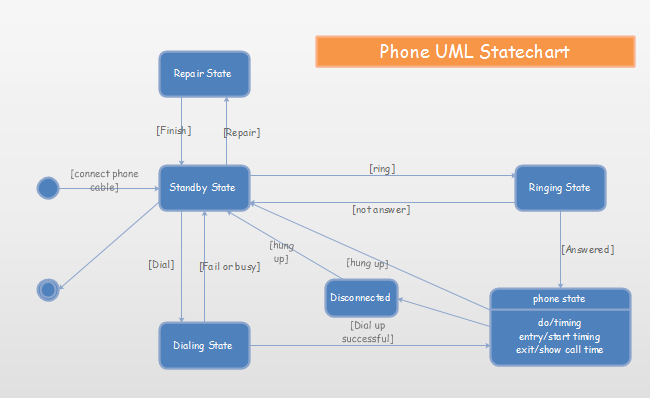
Activity Diagram
Activity Diagrams are used to illustrate the interconnected flow of different activities and actions (both in sequential form or in parallel type) in a system, and to display the steps involved in the execution of a use case. This type of UML diagram is widely used both in business modeling process and software development.
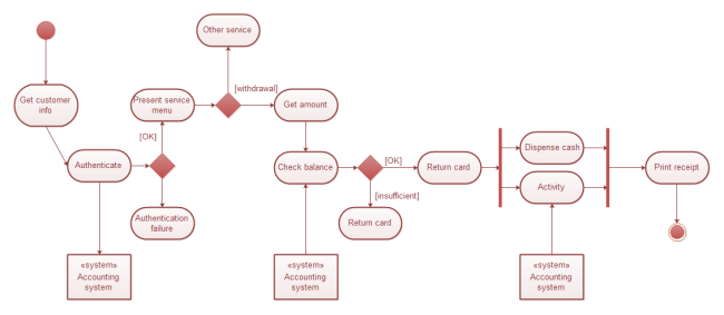
Use Case Diagram
A Use Case Diagram can be regarded as a good starting point for discussing project key actors and processes without going into too many implementation details. This UML diagrams is also the most popular type of the Behavioral UML diagram category, and is used to analyze the functionality (the use cases) and the interactions with different types of agents (actors) of a system. For business cases, enterprises may use such diagrams to check out the customer order system by monitoring the stock, product quality and so on. For daily life cases, Use Case diagrams are similar to the Hot Sale product list of your local supermarket. You know the product name and its prices according to the list when making your purchasing decision.
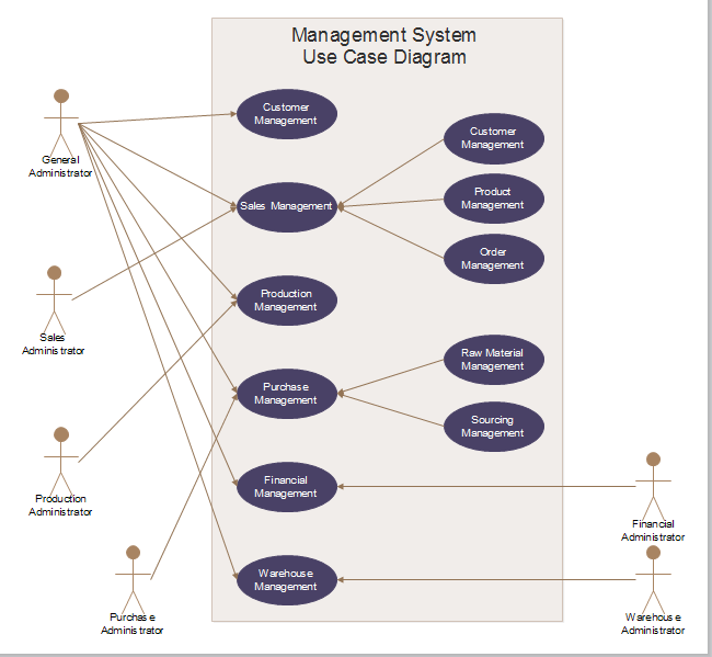
Sequence Diagram
A Sequence Diagram generally shows the interaction between objects in a sequential order. It is for users to document and understand requirements in a new system. In software development, this type of diagram is used to represent the architecture of a system.
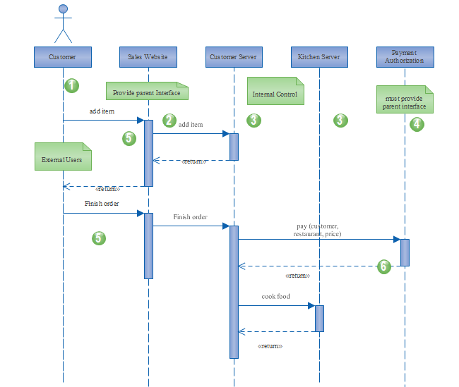
Communication Diagram (Collaboration Diagram)
A Communication Diagram is used to display sequenced communications between objects with the focus on primary objects and their relationships. Communication diagrams usually use number schemes and pointing arrows to show message flow. Moreover, compared with sequence diagrams, communication diagrams are much easier to be designed, but contains fewer details when drafting documentation for systems.
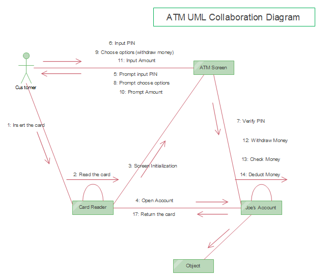
Timing Diagram
A Timing Diagram is a special form of the Sequence diagram that is used to show the behavior of objects over a certain time constraint. It is similar to the form of, for example, the history of iPhone development, or the growing trend of an international enterprise.
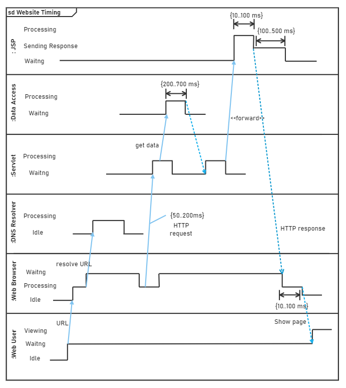
Interaction Overview Diagram
An Interaction Overview Diagram displays a sequence of behaviors and helps users simplify complex interactions (rectangular frames) into simpler forms in a system. It can be considered as a mixture of specialized activity and sequence diagrams, but Interaction Overview diagrams have more elements than Activity diagrams such as interaction, time constraint and more.
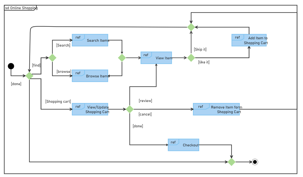
Activity diagram vs. Sequence diagram
The activity and the sequence diagrams are one of the types of the behavioral UML diagram and have a big contrast.
The Activity diagram shows us how the activity would be performed by each software component step-by-step. Plus, the communication of activities is also shown.
In the Sequence diagram , the objects and their correct order of performance are shown. Their performance is triggered when some events occur, but all objects work in a sequence form.
All-in-One Diagram Software
- Superior file compatibility: Import and export drawings to various file formats, such as Visio
- Cross-platform supported (Windows, Mac, Linux, Web)
Here are free-download UML diagram templates for you to easily understand all of these UML sub-categories. All of these are editable with EdrawMax . Click on any of them to see more details.
There are many UML diagram symbols in each of the UML categories. Among all of these symbols, the Class diagrams symbols (defining attributes and operations of classes), the Activity diagram symbols (used to show states and activities) and the Use case diagram symbols (shown with different types of arrows) are the most popular ones.
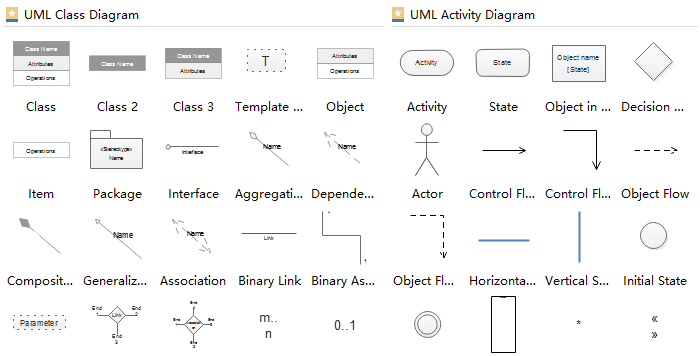
The process to start a UML-based development project is quite simple.
Finding what you have to make
The first thing you have to do is to find what you are developing. What kind of software is this? What would be its functionalities? What a user expects from this software.
Planning about your software
After knowing what your project is all about, get into the internal structure of the software. Calculate what type of classes you would include in the project. These classes contain properties, constructors, methods. How many objects would be there? How will the classes interact with each other? It is very complex work, so it's best to consult a software developer to plan your software architecture.
Making a UML Diagram
Now, after calculating the internal structure. Get the software to design your UML. You can't do it on paper with a pen or pencil. You can do it on EdrawMax that is the best-known diagram-making software. Use all the concepts of UML to make your UML diagram. See, how would you connect inherited classes, or how would you connect the property of a class used by the other class. Check if you are making a structure of the software or defining the behavior of your class, methods, objects, etc., then decide what type of UML you have to make, either structural UML diagram or behavioral UML diagram. Get training for making a UML.
Developing your project
Then finally start to develop the project. If you find any lacking, then don't worry. You have a UML. Use it and add your extensions. Track your project with the help of UML.
Picking up an easy-to-use UML diagram maker is important for everyone who wants to create a professional UML diagram. Luckily, EdrawMax is one of the most versatile UML daigram creators. Simply follow these steps to quickly create a professional-looking UML diagram.
Step 1: Open a preset UML diagram template or a blank drawing page for your work. Double-click one of the icons in the UML Model Diagram category to start creating.
Step 2: Drag and drop UML standard shapes from the built-in libraries. Adjust the shape size to fit the drawing board.
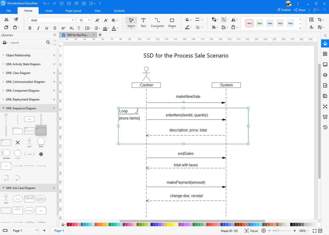
Step 3: Align or group UML shapes for the appropriate locations.
Step 4: Connect UML shapes by adding more connection points on the shapes or by using the preset relationship lines.

Step 5: Double-click to edit default shape text.
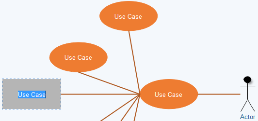
Step 6: Further format your UML diagram by changing the colors of shapes/lines, trying different diagram theme and adding background etc.
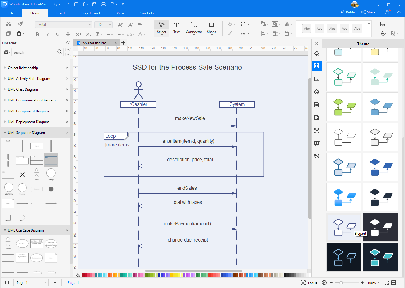
Step 6: Print, save to built-in personal/team cloud, or export to different formats including Visio, MS Office, PDF and more.
Create Your Own UML Diagrams Right Now!
Simply use EdrawMax for efficient UML diagramming. Enjoy Edraw's polished drawing board, extensive UML shapes built-in library, quick-exporting options for a wide range of formats including Visio, preset team and personal cloud account for your communications and the convenient drag-and-drop editor. Explore more features by clicking on the free download button at the end of this page.

Get Started! You Will Love This Easy-To-Use Diagram Software
EdrawMax is an advanced all-in-one diagramming tool for creating professional flowcharts, org charts, mind maps, network diagrams, UML diagrams, floor plans, electrical diagrams, science illustrations, and more. Just try it, you will love it!

UML diagram templates and examples
Reading time: about 4 min
- IT and Engineering
- Product development
We've compiled templates for three types of structural UML diagrams—class, component, and object diagrams—and three types of behavioral UML diagrams—activity, sequence, and use case diagrams. Find a template to document your systems faster than ever.
Want a primer before you get started? Learn about the 13 types of UML diagrams.
Class diagram templates Component diagram templates Object diagram templates Activity diagram templates Sequence diagram templates Use case diagram templates
Class diagram templates
The class diagram is one of the most commonly used diagrams in UML, as explained in depth in our guide on class diagrams . Software engineers and business professionals often choose class diagrams to map the structure of particular systems because they clearly display the various classes, attributes, operations, and relationships between objects.
In our examples below, you'll find that each class shape is labeled with its name in the first row, the second row displays each attribute of the class on a separate line, and the third row displays each operation on a separate line. From there, additional UML symbols are used to model the various interactions and objects involved within the process.

Component diagram templates
Component diagrams in UML are very similar to class diagrams. Both component and class diagrams display the structural relationship of software systems and their elements; however, component diagrams generally simplify the interactions within more complex systems. The components that make up this type of diagram are modular parts of the system that are inherently replaceable. Diagrams are structured this way so that the components can be easily replaced when needed.
The component diagram examples below show the structural relations between components in an online shopping system, library management system, and an ATM system. The connected circles, or “lollipop” symbols, represent realization relationships within the systems. Take a look at our examples below, and dive into our component diagram guide to become more familiar with component diagrams.

Object diagram templates
An object diagram in UML may look similar to a class diagram because it focuses on the attributes of a class diagram and how those objects relate to each other. For example, in the ATM template below, the class titles display the type of card, account, or action that the customer uses. The class attributes are all unique—in this case, the card has a specific number and PIN, the accounts and machines have their own specific numbers and amounts, and actions have specific transaction numbers.
Refer to our object diagram guide if you need more insight. With the rest of our object diagram examples, you'll see that these UML diagrams aren't just limited to banking systems. Try one out.

Activity diagram templates
Activity diagrams in UML are a leading subset of behavioral diagrams. They display the functionalities of various activities and flows in business processes and software systems. With UML-specific symbols , you can map out the start point, end point, and all the merging and interactions in between your process flow. See our guide on activity diagrams if you need additional information.

Sequence diagram templates
Many project managers and engineers use sequence diagrams in UML to get a better idea of how tasks within a project will function, overlap, and move between objects or components. Create sequence diagrams to display interactions between objects and the order in which those interactions occur.
You can read our full guide on sequence diagrams for additional reference. While the examples below cover UML sequence diagrams, Lucidchart still has the shapes and features you need to model code-based sequence diagrams as well.
(P.S. You can save even more time when you generate UML sequence diagrams from text markup in Lucidchart. Learn more about this feature .)

Use case diagram templates
With a UML use case diagram, you can create a broad, high-level view of the relationship between use cases, actors involved, and systems being performed. Take a look at our use case diagram guide to learn more about the benefits of use case diagrams and the shapes involved.
As you can see from the examples below, use cases are represented by oval shapes, and the lines then show at which point an actor participates and interacts with their corresponding use case. You can see where each actor is involved within the entire process (and where they're excluded). For instance, in one of the examples, a truck driver needs to know the location information but doesn't need to be involved at any other part of the process within a successful inventory system.

UML diagrams may look complicated, but the process of building one doesn't have to be. Click on any of the templates above to get started.
Build UML diagrams to navigate source code and plan new features—our UML diagram tool makes the process simple and collaborative.
Lucidchart, a cloud-based intelligent diagramming application, is a core component of Lucid Software's Visual Collaboration Suite. This intuitive, cloud-based solution empowers teams to collaborate in real-time to build flowcharts, mockups, UML diagrams, customer journey maps, and more. Lucidchart propels teams forward to build the future faster. Lucid is proud to serve top businesses around the world, including customers such as Google, GE, and NBC Universal, and 99% of the Fortune 500. Lucid partners with industry leaders, including Google, Atlassian, and Microsoft. Since its founding, Lucid has received numerous awards for its products, business, and workplace culture. For more information, visit lucidchart.com.
Related articles

Many software engineers use diagrams to architect new applications and systems and to prepare documentation for troubleshooting and training. Our engineers at Lucid Software are no different. They diagram as they work hard to make diagramming (and designing on Lucidpress) easier for you. Check out how our engineers have applied Lucidchart in various aspects of their jobs.

Working visually shouldn’t mean more work for you. Find out how to automate your diagramming with Lucidchart to help your teams do more faster.
Bring your bright ideas to life.
or continue with
Filter by Keywords
10 UML Diagram Templates & Examples to Visualize Your Project
Robert Hales
ClickUp Contributor
February 13, 2024
Building a project without a diagram or a blueprint can feel like assembling a jigsaw puzzle in the dark.
With UML diagram software , we switch the lights on! 💡
This article presents 10 exceptional UML diagram templates, each designed to visualize your project and lead you smoothly to success.
What is a UML Diagram Template?
What makes a good uml diagram template, 1. clickup uml activity template, 2. clickup uml class diagram template, 3. clickup swimlane flowchart template, 4. clickup data flow diagram template, 5. clickup project charter template, 6. clickup company processes document template, 7. clickup sales process template, 8. clickup project network diagram template, 9. clickup marketing team processes template, 10. clickup block diagram template.
A UML diagram template is a tool you can use as a starting point for creating a customized UML diagram. It’s a visual representation showing how parts of a program, system, or process work together.
UML stands for Unified Model Language, which is a visual language with a specific set of rules used for drawing UML diagrams.
Think of a UML diagram like a map, but instead of showing where specific points, objects, and places are, it shows how they’re connected. There are many types, but here are just a few UML diagram examples you’ll most commonly find:
- Class diagrams : A class diagram shows the different classes of things in a program and how they relate to each other. They are often used in agile methodology
- Sequence diagrams : You can use sequence diagrams to understand how things happen in a program or business process, one step at a time
- Activity diagrams : The purpose of activity diagrams is to analyze each step in a process and determine how each of the steps are connected
- Behavioral UML diagrams: Behavioral diagrams describes how your system interacts with both itself and other systems based on the effects of time or precipitating events
- Component diagrams: Break down the component objects of your system—think files, libraries, and executables—with component diagrams so you have a better fundamental understanding of the parts that make your system tick
- Deployment diagrams: This type of UML diagram maps out the physical hardware of your system, and how it relates to the software that runs on that architecture
- Object diagrams: Software teams use an object diagram to represent a snapshot of one piece of their system. This snapshot captures that object at a certain time and in a particular state of being to make that one instance easier to study and understand
- Structural UML diagrams: Structural UML diagrams give you an overview of the entire system. You get a bird’s eye view of your classes, objects, packages, and components so you get a better understanding of how each of those categories relates to the other.
UML diagrams are often used by software engineers and developers to understand processes, organize data, and decipher relationship lines. Additionally, these maps and sequence diagrams are often created on advanced software development project management tools .
But, as you’ll see in our review below, UML diagrams are also a great way to create diagram processes for project managers, marketing teams, and other business professionals to visualize business processes.
The best UML diagram templates (Unified Modeling Language) are a visual unified modeling language that helps people visualize processes, complex programs, or systems. Here are six things to look for when choosing UML diagrams:
- Clarity : It should be easy to understand and clearly show the different parts of a program, and how these parts work together
- Accuracy : It should correctly represent the program. So, all the details in the diagram should match exactly with what the program does
- Easy to use : These diagram templates should be simple to use so people can easily visualize their systems and processes
- Easy to update : As people keep improving their software, they need to change the diagrams. A good template makes changes and customizations easy
- Sharing : It should be easy to share with others. That way, everyone working on the program can see and understand it
- Mind Mapping: Whiteboards make great UML diagram types and are a bonus because they can also act as mind-mapping software

In short, a good UML diagram makes creating and understanding programs (or software systems and processes) easier.
10 UML Diagram Templates to Use in 2024
As we move through 2024, mastering project management with the right software systems and tools has never been more critical. These 10 exceptional UML diagram templates will help streamline your workflows and organize your projects before the year is out.
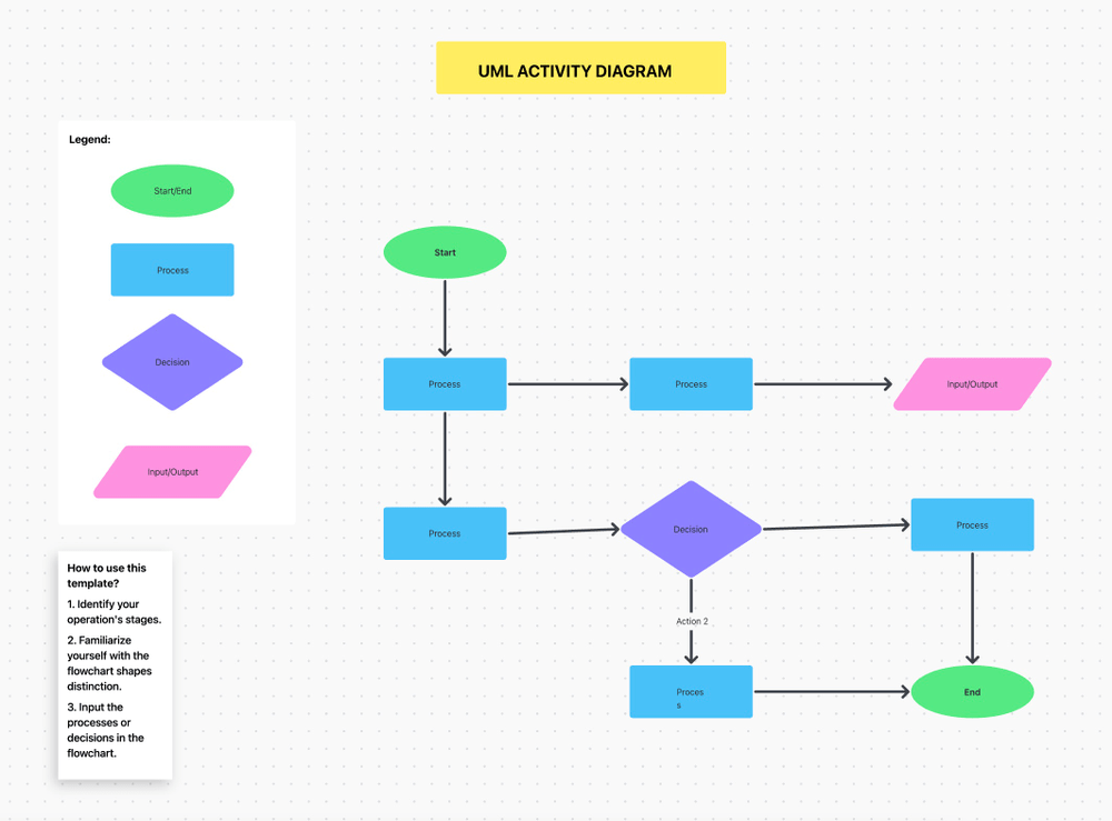
Looking for an intuitive, visual way to map out and design processes within a software development project? The UML Activity Template by Clickup is here for you!
The UML activity diagram, set in Whiteboard view, is commonly used to analyze software.
The template gives everyone on your team an overview of the system’s structure.
So, if you’re wanting to create UML diagrams that provides a crystal-clear, visual look at your systems, ClickUp’s UML activity diagram is a great bet!
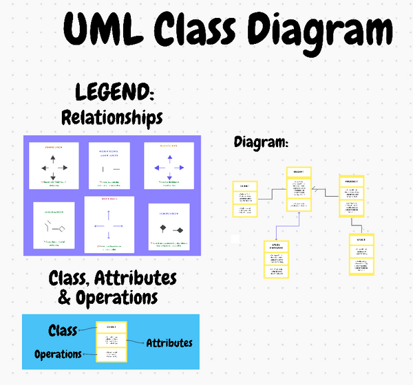
The UML Class Diagram Template by ClickUp gives you all the tools you need to create, share, and track class diagrams.
Visualize, collaborate, and store your diagrams in a way that keeps them organized and clear.
This template is great for modeling complex systems and applications in UML diagrams.
Present complex object-oriented systems within a Whiteboard setting system that allows you to:
- Organize classes into logical groupings
- Identify relationships between classes
- Compare multiple versions of a system
- Save diagrams in an organized database
This template provides customizable views, statuses, and fields so you can easily tailor views and information.
And, its project management functions help improve tracking with features like tagging, nested subtasks, priority labels, and more.
And the best part? You can do it together with your team, thanks to real-time collaboration.
So, for all builders of computer programs, these UML diagrams are an amazing tool. Give this one a try, for free, today!
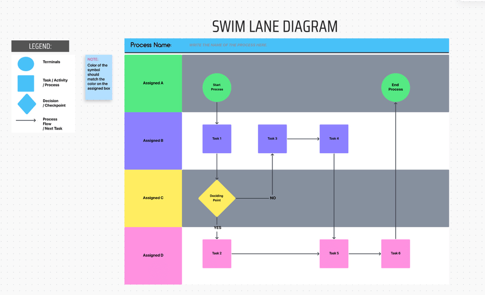
To map out workflows and identify roles and responsibilities within a project, you need a tool to help visualize the overall process. That’s where the Swimlane Flowchart Template by ClickUp shines.
A swimlane template structures its flowchart in the shape of a swimming pool, using vertical and horizontal shapes that look like lanes. 🏊
This template is a flowchart software tool, in Whiteboard format, that allows you to:
- Visualize project steps, people, and departments
- Identify roles and responsibilities
- Clarify complex processes
- Improve process understanding
- Collaborate with team members and stakeholders
These features make working on a project so much easier. If you want to make your projects feel simple and natural, try ClickUp’s Swimlane Flowchart Template!
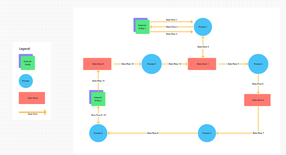
The Data Flow Diagram Template by ClickUp is a super helpful tool that allows systems analysts, software engineers, developers, and project managers to better understand the information moving through their systems and processes.
A Data Flow Diagram (DFD) is like a map of a city but for information in a computer system. Instead of roads and buildings, it shows how information, or ‘data’, moves from one place to another inside a computer program.
You can see where the information comes in, like cars entering the city. Then, you can follow its journey as it gets processed or changed, just like cars driving around different city blocks. 🏙️
Finally, you can see where the data leaves, like cars getting on the offramp to leave town. Ready to diagram your systems and processes? Download ClickUp’s Data Flow Diagram now and make your systems and processes as visual as a city map.
The Project Charter Template by ClickUp helps you record the key elements of a project. A Project Charter is a critical project document that formally starts and concludes a project.
It helps you clarify a project’s scope, objectives, resources, and the key people involved. This template helps you formally identify key structural elements within a project such as:
- Your project’s purpose
- Your project’s goals
- Your team members and their roles
- Success criteria
Make sure everyone understands the important details of your software project’s plan so there’s no confusion when it’s time for project execution . The Project Charter Template is like a compass, pointing you and your team in the right direction along the way.
Ready to start your journey? Download the Project Charter Template by ClickUp!

The Company Processes Document Template by ClickUp is like an easy-to-use recipe book for all the tasks in your company.
The template helps you record step-by-step instructions that record all your business processes for things like:
- Hiring new team members
- Teaching new people their jobs
- Making sales
- Handling the company’s money 💰
Using the company processes template will help your company maintain the kind of consistency and efficiency it needs to grow.
Ready to run your company as smoothly as a Michelin Star kitchen? Don’t miss out on the secret ingredient: ClickUp’s Company Processes Document Template. Download it now and start dishing up some serious organization and consistency.
The Sales Process Template by ClickUp is a fun diagram that helps your team sell better.
UML diagram types like this will walk you through all the steps required to create documentation and for sales process mapping. It will help you support your sales team by outlining exactly what steps they should take to nurture leads from prospect to customer.
Don’t leave your salespeople in the dark. Instead, diagram a well-organized sales process guide that outlines your brand’s guidelines and explains how to:
- Identifying target customers and finding leads
- Communicating with potential customers
- Offering deals
- Making the sale
This Sales Process Template Includes eight custom fields:
- Opportunity
- Customer Email
- Qualify Lead
- Contact Number
- Sales Phase
- Customer Type
- Sales Status
This template helps you diagram all these steps so your team is clear, consistent, and successful at converting leads to customers. So if you’re a team leader and want your team to sell like champs, try ClickUp’s Sales Process Template today!
Is your project starting to look like a pile of Legos scattered across random departments? We’ve got you covered! The Project Network Diagram Template by ClickUp allows you to visually represent the full sequence diagram of tasks and activities in any project.
A Project Network Diagram makes it easier to communicate the moving parts of a software project so the whole team understands their role in the entire process. It helps keep things on track so you can avoid falling behind on projects.
Whether it’s an engineering project, case diagram, business plan, marketing strategy, or something in between, this template helps you clarify the big picture. Use it to help create a visual diagram for things like:
- A sequence diagram of activities
- How tasks are connected
- What resources each task needs
- Where potential delays might occur
- What the global task relationships look like
Download the template today and start reducing errors, strengthening consistency, and communicating progress updates to the people that matter.
Bonus: Affinity diagram templates & affinity diagram software !

Are you looking to create step-by-step instructions for all your SOP (Standard Operating Procedures) repeatable processes?
The Marketing Team Processes Template by ClickUp can set you up with an organized, efficient blueprint for doing just that.
This template includes seven pages to cover a variety of marketing processes:
- Marketing Team Processes
- Campaign Process
- Blog Process
- Design Process
- Creative Processes
- Video Process
Finally! Building an instruction library for your marketing team is now quicker, easier, and more efficient with ClickUp’s Marketing Team Processes Template. Start diagramming today!
The Block Diagram Template by ClickUp helps engineers create a visual representation of the main components and functions of a system.
Whether you need it for a sequence diagram, context diagram , process flow diagram, software design interaction overview diagram, object diagram, electronic design, or hardware design, these UML diagrams have got your back.
Enjoy designing and remember: time is of the essence, so don’t wait to simplify your life. Download the ClickUp Block Diagram Template now and step into a more organized, efficient future.
Exploring the Power of UML Diagram Templates
We’ve shown you 10 awesome UML diagrams to help visualize your projects, systems, and programs. Just like turning on a light in a dark room, these diagram templates can help you see exactly what you’re doing!
UML diagrams aren’t just for people who build computer programs; they’re great for managers, marketers, and many others too. What type of UML diagram will you use? Whichever diagrams you need, ClickUp has the tools to make it happen!
With our amazing types of UML diagrams and templates, planning and visualizing your projects can be easier and more efficient.
Don’t just take our word for it, give ClickUp a try today !
Questions? Comments? Visit our Help Center for support.
Receive the latest WriteClick Newsletter updates.
Thanks for subscribing to our blog!
Please enter a valid email
- Free training & 24-hour support
- Serious about security & privacy
- 99.99% uptime the last 12 months
How to Make a UML Diagram Online in Minutes?

7 Useful Methods to Create UML Diagrams
- Visual Studio
- MySQL Workbench
Create UML diagram online (GitMind)
The first solution we have here is GitMind. This is a free online mind mapping and collaboration tool that can be used conveniently. This tool can help users to create a mind map, flowchart, organization chart, swimlane, analysis, and even UML diagram. Aside from that, it also offers hundreds of editable templates that you can use for education, business, product, engineering, sales, operations, and others. Moreover, if you want to create your own UML diagram, you can do so. So here are the steps you can follow on how to make a UML diagram.
- The first thing you need to do is to go on your favorite browser and visit the official page of the tool. From here, you will see the “Get Started” button then click it.
- Hit the “UML” option at the left side of the page, and choose the desired template to use. If you wish to create a new flowchart, simply click the “New Flowchart”.
- You will find the shapes and symbols on the left side of the tool, choose the shape or symbol you need then place the cursor on the canvas then start to draw.
- Customize the diagram depending on your need, then save or export it when you are done.
Create UML diagram in Visio
Another way to draw UML diagrams is by using Visio. This is another web-based program that allows you to draw a different variety of diagrams which include UML diagrams, flowcharts, 3D maps, and many more. In addition to that, it offers a wide range of built-in shapes, objects, and stencils. In fact, you can create your own shapes and use them on your diagram. To utilize this software, see the steps given below.
- Open the tool on your favorite browser.
- In the gallery, scroll down the UML class row, you can select a blank template or use the sample diagrams given and edit the content to create a UML diagram.
- When you are done, save the diagram.
Create UML diagram in PowerPoint
PowerPoint is one of the popular presentation software which is commonly used by business people and students to create slides for presentations. in addition to that, users can add different content such as diagrams, pie charts, images, and other shapes and symbols. With that, you can create a UML diagram in just a few clicks. Here is the guide on how you can do it.
- Launch the software on your computer then, hit “New blank presentation”.
- Next, hit the “Insert’ options and click shapes to add shapes and other symbols that need to add to your diagram. Edit the diagram according to the information needed.
- When you are done, save the diagram by clicking the “File” then “Save”.
Create UML diagram in Word
An alternative way to draw UML diagrams is by using Word. This software is created by Microsoft similar to PowerPoint. This is a great tool to create a document that is needed for businesses and schools. It can be a letter, resume, catalog, certificates, receipts, report or paper, proposal, and a lot more. Aside from these, users can make a UML diagram, flowchart, and a lot more. See the steps listed below on how this tool works.
- Open a blank Word document to start your UML diagram.
- Click “Insert” then “Text Box” and hit the “Simple Text Box” then edit the text. Enter the name of the classes and other class components. Insert other shapes and symbols for your diagram.
- Once you are finished, save it.
Create UML diagram in Visual Studio
Next on the list in Visual Studio. This is commonly used to develop computer programs, websites, web services, web apps, and even mobile apps. In addition to that, it enables you to create, design, and edit UML diagrams and other types of diagrams. Follow the guide below.
- Open the software and go to the “Solution Explorer” and right-click the project node then choose “Add New Item”.
- From here, click the “Common Items” then “General” and choose the template for your diagram. You can drag shapes, symbols, and lines to the diagram.
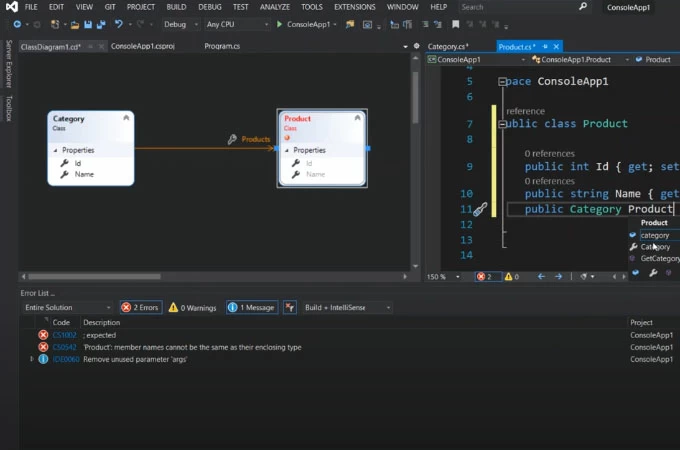
- Once all set, save the diagram.
Create UML diagram in Eclipse
Eclipse is mostly written in Java and it is used for developing Java applications. It can also use to develop applications in other languages. Aside from that, it is also used to create a UML project for any Java project. Below are the simple steps you can follow to create a UML diagram.
- Launch the Eclipse software the choose the java project you wish to create a UML project. Right-click the project and select “Open Visual Paradigm” from the Menu.
- Select the “Project Structure” and choose “Create in a default path”.
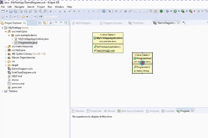
- After that, hit the “OK” button.
Create UML diagram in MySQL Workbench
Last but definitely not least is the MySQL Workbench. This is a visual tool that can be used by developers and database architects that provides data modeling, user administration, and a lot more. Besides, it is very helpful to have a visual representation when you are designing a database. With this tool, you can create a UML diagram from a downloaded SQL file. Here are the steps that you can follow.
- Open the MySQL Workbench then choose “File’ and “New Model” from the top menu. Next, click “File” and “Import” and click ‘Reverse Engineer MySQL Create Script”.
- Specify the SQL file you need then arrange and connect the tables depending on your liking.
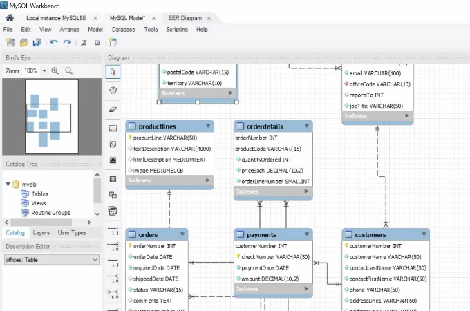
- When you’re done editing, export the diagram.
All the mentioned tools above can surely help you create a UML diagram with ease. You can try all these solutions however, if you are into practicality, choose GitMind since it is very convenient and free to use.
Related posts:
- Best 8 Free Online UML diagram tools in 2024
- What is A Probability Tree Diagram and Real Life Uses
Leave a Comment
Comment (0).
This website uses cookies that are essential for the operations of this website and its core functions. Other cookies will only be placed with your consent. For more details visit our Cookies Policy .
UML Class Diagrams: Basic Concepts
Jan 05, 2020
360 likes | 384 Views
UML Class Diagrams: Basic Concepts. Extracted from textbook: Object Oriented Modeling and Design with UML M. Blaha, J. Rumbaugh. Objects. The purpose of class modeling is to describe objects. An object is a concept, abstraction or thing that has meaning for a domain/application.
Share Presentation
- association ends
- association end
- attributes values
- class object representation
- superclass holds common attributes

Presentation Transcript
UMLClass Diagrams: Basic Concepts Extracted from textbook: Object Oriented Modeling and Design with UML M. Blaha, J. Rumbaugh
Objects • The purpose of class modeling is to describe objects. • An object is a concept, abstraction or thing that has meaning for a domain/application. • Some objects have real world counterparts while others are conceptual entities. • The choice of objects depends on judgment and the nature of problem. • ِAll objects have identity and are distinguishable.
Classes • An object is an instance – occurrence – of a class • ِA class describes a group of objects with the same properties (attributes), behavior (operations), kinds of relationships, and semantics. • The objects in a class share a common semantic purpose, above and beyond the requirement of common attributes and behavior. • By grouping objects onto classes we abstract a problem.
UML representation of classes/objects: • UML: Unified Modeling Language (OMG Standard): O.O Visual Modeling language • Class/object representation
Values and attributes • Value : piece of data. • Attribute: a named property of a class that describes a value held by each object of the class. • Attributes may be discovered by looking for adjectives or by abstracting typical values. • Don’t confuse values with objects: • An attribute should describe values, not objects. • Unlike objects, values lac identity
UML representation
Object identifiers • Objects identifiers are implicit. • Objects belonging to the same and having the same attributes values may be different individual objects.
Operations and Methods • An operation is a function or procedure that may be applied to or by objects in a class. • Each operation has a target object as an implicit parameter. • All objects in a class share the same operations. • The behavior of the operation depends on the class of its target. • The same operation may apply to many different classes. Such an operation is POLYMORPHIC.
Operations and Methods • A method is the implementation of an operation for a class. • A different piece of code may implement each method. • An operation may have arguments in addition to its target object. These arguments may be placeholders for values and/or for objects. • When an operation has methods on several classes these methods must have the same SIGNATURE: number and types of arguments, type of result value.
Links and Association concepts • A link is a physical or conceptual connection among objects. • Most links relate two objects, but some links relate three or more objects. • A link is defined as a tuple, that is a list of objects. • A link is an instance of an association. • An association is a description of a group of links with common structure and semantics. • Association is denoted by a line. Its name is optional if the model is unambigious.
Associations are inherently bi-directional. The association name is usually read in a particular direction but the binary association may be traversed in either direction. • ِ A reference is an attribute in one object that refers to another object.
Multiplicity • It specifies the number of instances of one class that may relate to a single instance of the associated class. • UML diagrams explicitly list multiplicity at the end of association lines. • Intervals are used to express multiplicity: • 1 (exactly one) • 0..1 (zero or one) • 1..* (one or more) • 0..* (zero or more) • 3..5 (three to five inclusive)
Association Ends • Associations have ends. They are called ‘Association Ends’. • They may have names (which often appear in problem descriptions).
Association Ends • Use of association end names is optional. • But association end names are useful for traversing associations. • ِAssociation end names are necessary for for associations between objects of the same class.
Example of association ends use
Association: ordering, bag, sequence • On a ‘many” association end, sometimes, it is required that objects have an explicit order. • In this case the ordering is an inherent part of the association • Example:
Association: ordering, bag, sequence • Ordinary a binary association has at most one link for a pair of objects • However we can permit multiple links for a pair of objects by annotating an association end with {bag} or {sequence} • A bag is a collection of elements with duplicates allowed. • A sequence is an ordered collection of elements with duplicates allowed
Association class • UML offers the ability to describe links of association with attributes like any class. • An association class is an association that is also a class.
Association class • Examples:
Association class • Example
Qualified Association • A qualified association is an association in which an attribute called Qualifier disambiguates the objects for a ‘many’ association’ end. • A qualifier selects among the target objects, reducing the effective multiplicity fro ‘many’ to ‘one’. • Both below models are acceptable but the qualified model adds information.
Qualified Association • Example:
Generalization/Inheritance • Generalization is the relationship between a class (superclass) and one or more variations of the class (subclasses). • Generalization organizes classes by their similarities andtheir differences, structuring the descriptions of objects. • A superclass holds common attributes, attributes and associations. • The subclasses adds specific attributes, operations, and associations. They inherit the features of their superclass. • Often Generalization is called a “IS A” relationship • Simple generalization organizes classes into a hierarchy. • A subclass may override a superclass feature (attribute default values, operation) by redefining a feature with the same name. • Never override the signature of methods.
Use of generalization • Used for three purposes: • Support of polymorphism: • polymorphism increases the flexibility of software. • Adding a new subclass and automatically inheriting superclass behavior. • Structuring the description of objects: • Forming a taxonomy (classification), organizing objects according to their similarities. It is much more profound than modeling each class individually and in isolation of other similar classes. • Enabling code reuse: • Reuse is more productive than repeatedly writing code from scratch.
Aggregation • Aggregation is a strong form of association in which an aggregate object is made of constituent parts. • The aggregate issemantically an extended object that is treated as a UNIT in many operations, although physically it is made of several lesser objects. • Aggregation is a transitive relation: • if A is a part od B and B is a part of C then A is also a part of C • Aggregation is an antisymmetric relation: • If A is a part of B then B is not a part of A.
Aggregation versus Association • Aggregation is a special form of association, not an independent concept. • Aggregation adds semantic connotations: • If two objects are tightly bound by a part-whole relation it is an aggregation. • If the two objects are usually considered as independent, even though they may often be linked, it is an association. ِ • Discovering aggregation • Would you use the phrase part of ? • Do some operations on the whole automatically apply to its parts? • Do some attributes values propagates from the whole to all or some parts? • Is there an asymmetry to the association, where one class is subordinate to the other?
Aggregation versus Composition • Composition is a form of aggregation with additional constraints: • A constituent part can belong to at most one assembly (whole). • it has a coincident lifetime with the assembly. • Deletion of an assembly object triggers automatically a deletion of all constituent objects via composition. • Composition implies ownership of the parts by the whole. • Parts cannot be shared by different wholes.
Aggregation versus Composition Composition is a strong form of aggregation where: • Deletion of a “whole” triggers automatically deletion of all its “parts”.(Lifetime) • “Parts” are included in at most one “whole” at a time. (Sharing)
Propagation of operations • Propagation is the automatic application of an operation to a network of objects when the operation is applied to some starting object. • Propagation of operations to parts is often a good indicator of propagation.
- More by User
UML Class Diagrams
UML Class Diagrams. UML Class Diagrams. Represent the (static) structure of the system General In Java In C++ Name Name Name State Variables Members Behavior Methods Functions. Relationships Between Classes. Association Permanent, structural, “has a”
1.5k views • 42 slides

Some Basic Concepts of Energy
Some Basic Concepts of Energy. Prepared for FYF 101J - Alternative Energy. Kenneth M. Klemow, Ph.D. Wilkes University. Overview of topics. Basic energy concepts Historic phases of energy production and supply Terminology pertaining to energy. Basic energy concepts. What is energy?.
535 views • 19 slides

Chapter 2. The Basic Concepts of Set Theory. © 2008 Pearson Addison-Wesley. All rights reserved. Chapter 2: The Basic Concepts of Set Theory. 2.1 Symbols and Terminology 2.2 Venn Diagrams and Subsets 2.3 Set Operations and Cartesian Products 2.4 Surveys and Cardinal Numbers
818 views • 77 slides

OO domain modeling with UML class diagrams and CRC cards
OO domain modeling with UML class diagrams and CRC cards. CSE432 Prof Glenn Blank. What is a Domain Model?. Illustrates meaningful conceptual classes in problem domain Represents real-world concepts, not software components
353 views • 34 slides

Chapter 3 Class Diagrams: The Essentials
Chapter 3 Class Diagrams: The Essentials. Terms and Concepts. A class is ... The most important building block of any object-oriented system. A description of a set of objects that share the same attributes and behaviors. A blueprint for creating an object.
318 views • 21 slides

UML CLASS DIAGRAMS
UML CLASS DIAGRAMS. Basics of UML Class Diagrams. What is a UML class diagram? Imagine you were given the task of drawing a family tree. The steps you would take would be: Identify the main members of the family Identify how they are related to each other
534 views • 20 slides

Object-oriented modeling Activity diagrams
Object-oriented modeling Activity diagrams. Karolina Muszyńska. Based on : S. Wrycza, B. Marcinkowski, K. Wyrzykowski „Język UML 2.0 w modelowaniu SI”. Object Modeling. Dynamic view – activity diagrams role basic concepts advanced concepts examples. Activity Diagrams – role.
413 views • 21 slides

Object-oriented modeling Class/Object Diagrams
Object-oriented modeling Class/Object Diagrams. Karolina Muszyńska. Based on : http://www.csun.edu/~dn58412/IS431/IS431_SP13.html S. Wrycza, B. Marcinkowski, K. Wyrzykowski „Język UML 2.0 w modelowaniu SI”. Object Modeling – class/object diagrams. Static view - class/object diagrams
390 views • 22 slides

Design Class Diagrams & Intro to Sequence Diagrams
Design Class Diagrams & Intro to Sequence Diagrams. CIS 480, Spring 2012. Adding Objects at the Model Level. Can Add an Object to the MODEL without putting it in a diagram Right Click on Top package for the model & from the new menu select the type of object. Then complete its specifications .
311 views • 15 slides

UML Class Diagrams. Chapter 16 Applying UML and Patterns Craig Larman. Objective. Create design class diagrams (DCDs). Identify the classes, methods, and associations to show in a DCD. . Class Diagrams. The UML has notation for showing design details in static structure. Class diagrams
877 views • 37 slides

UML CLASS DIAGRAMS. Basics of UML Class Diagrams. What is a UML class diagram? Imagine you were given the task of drawing a family tree . The steps you would take would be: Identify the main members of the family Identify how they are related to each other
445 views • 29 slides

Object-oriented modeling Communication diagrams
Object-oriented modeling Communication diagrams. Karolina Muszyńska. Based on : S. Wrycza, B. Marcinkowski, K. Wyrzykowski „Język UML 2.0 w modelowaniu SI”. Object Modeling. Dynamic view – communication diagrams role of communication diagrams basic concepts
228 views • 11 slides

Unit I: Basic Economic Concepts
Unit I: Basic Economic Concepts. 3 FACTS!. Econ is a skills based course. Learning methodology resembles algebra more than history. You MUST complete assignments BEFORE class Class time should be about sharpening skills, rather than just introducing/reviewing concepts.
1.41k views • 120 slides

Introduction to Thermodynamic Diagrams
Introduction to Thermodynamic Diagrams. How thermodynamic diagrams are used to forecast thunderstorms?. Introduction to Thermodynamic Diagrams. Outline: Basic Idea of Thermodynamic Diagrams Possible Diagrams Skew-T Log-P Diagram Rawinsondes Dropsondes Skew-T Applications.
893 views • 26 slides
Use Cases. Week 8 CMIS570. Refresher – Class Diagrams. Appointment scheduling example Car Rental example Fitness Class example. UML diagrams. 9 diagrams Used throughout SDLC Use consistent syntax and notation. Key building block is the use-case. Use-Case.
408 views • 22 slides

Object Oriented Concepts
Object Oriented Concepts. Introduction. Agenda. Design, Software design Definitions of OO constructs Class Diagrams, Sequence Diagrams, State Diagrams Some principles of design Case Study Back To OO OO in maintenance projects What it is not! It is not a UML session
343 views • 14 slides

Modeling with UML
Chapter 2 Object-Oriented Software Engineering: Using UML, Patterns, and Java, 2 nd Edition By B. Bruegge and A. Dutoit Prentice Hall, 2004. Modeling with UML. Modeling with UML. What is UML? Use case diagrams Class diagrams Sequence diagrams Statechart diagrams Activity diagrams.
678 views • 47 slides
The standard state diagrams for the HV FSM
The standard state diagrams for the HV FSM. Some introduction concepts on FSM The JCOP document for the standards The standard state diagrams for the HV FSM Conclusions. Basic concepts for the FMS.
172 views • 7 slides

IS0514 Lecture Week 10
IS0514 Lecture Week 10. Other UML Diagrams in Business Modelling. So far. Modelling Best Practice Development Use Case Diagrams Use Case Descriptions Class Diagrams CRC Cards This week Other UML Diagrams. Structure Diagrams Class Object Package Deployment Component
562 views • 22 slides

UML. Overview. UML Diagrams to be Covered. Class Diagrams Use Case Diagrams Collaboration Diagrams Sequence Diagrams Package Diagrams Component Diagrams Deployment Diagrams Activity Diagrams State Diagrams. Class Diagrams. Are the most fundamental UML Diagram.
923 views • 21 slides
Basic Statistical Concepts
Basic Statistical Concepts. Psych 231: Research Methods in Psychology. Turn in Journal summary #2 in class on Wednesday (moved from turning in last week in labs). There are three main measures of center Mean (M) : the arithmetic average Add up all of the scores and divide by the total number
530 views • 31 slides
Intro to UML - OO Class Diagrams
Intro to UML - OO Class Diagrams. Week 5 CMIS570. Plan for Tonight. Object terms Unified Modeling Language history Class Diagrams Intro to Oracle Oracle ERDs. Object-Oriented Analysis & Design. Object-oriented analysis Defines all of the types of objects that do the work of the system
467 views • 28 slides
Multi-Layered Application
Uml model diagram example.
An example of UML model diagram representing a model of a layered application , based on the Microsoft Application Achitecture Guide, 2nd Ed.
According to the Guide, layers are concerned with the logical division of components and functionality, and do not take into account the physical location of components, whereas tiers describe the physical distribution of the functionality and components on separate servers, computers, networks, or remote locations. Layers can be located on different tiers, or they may reside on the same tier.
Application model shows several layers - presentation layer, services layer, business, data, and cross-cutting layers. All layers are represented as UML models .
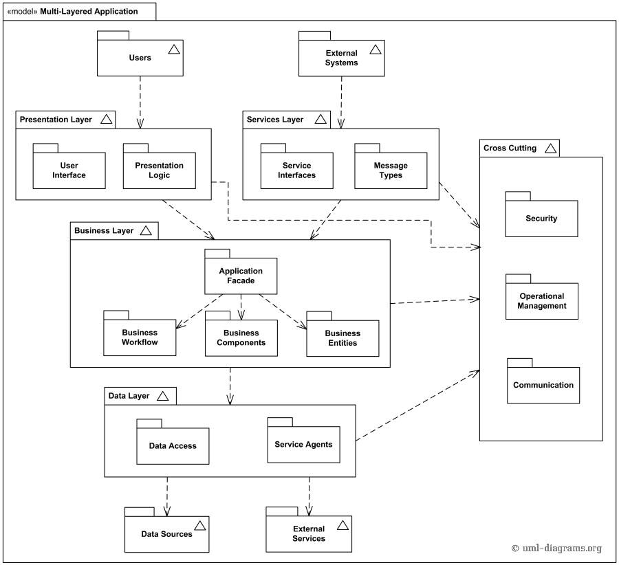
Multi-layered application UML model diagram example.
Users and external systems are also represented as models, and communicate with presentation and services layers, correspondingly. Diagram also shows data sources such as relational databases and web service agents that provide access to data and external or remote services that are consumed by the application.
Cross-cutting layer contains common functionality that spans layers and tiers. This functionality typically supports authentication, authorization, caching, communication, exception management, logging and instrumentation, and validation. Such functionality is generally described as crosscutting concerns .
You are using an outdated browser. Please upgrade your browser to improve your experience.
UML Diagrams
Our vast library of UML Diagrams PowerPoint templates are professionally designed to elevate your presentation style in any professional meeting. The collection provides a comprehensive framework to professionals across industries to streamline their efforts, ideas and overall message. The fully editable UML Diagrams PowerPoint and Google Slides templates breathe life into complex facts, figures and information and present them in an engaging manner to ensure a long lasting impact on your audience’s minds.
Our extensive collection of UML Diagrams PPT templates promote productivity and convenience when it comes to its applications. These templates have been thoughtfully designed to ensure maximum visual impact. Explore our collection of UML Diagrams presentation templates and download the perfect template to take your presentation to new heights!
- Price <= $5.99
- Price > $5.99
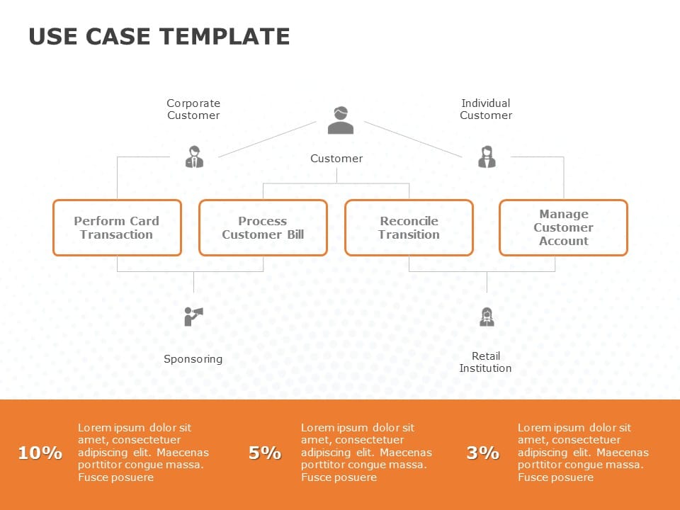
Use Case 04 PowerPoint Template
Login to use this feature
Add-to-favs lets you build a list for inspiration and future use.
Log in now to start adding your favs.
If you don't have one. A free account also gives you access to our free templates library
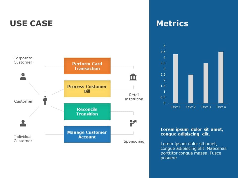
Use Case 02 PowerPoint Template

Online Purchase Use Case Diagram PowerPoint Template

Use Case 01 PowerPoint Template
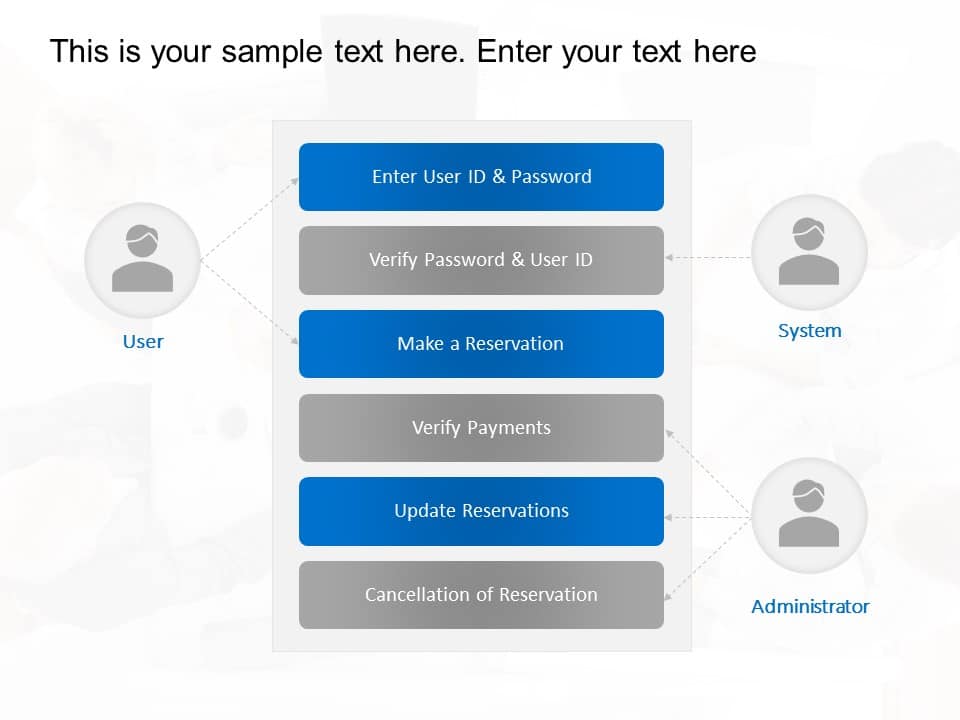
Use Case Diagram for Login PowerPoint Template

Use Case Diagram PowerPoint Template
Uml diagrams powerpoint templates for presentations:.
The UML Diagrams PowerPoint templates go beyond traditional static slides to make your professional presentations stand out. Given the sleek design and customized features, they can be used as PowerPoint as well as Google Slides templates . Inculcated with visually appealing unique and creative designs, the templates will double your presentation value in front of your audience. You can browse through a vast library of UML Diagrams Google Slides templates, PowerPoint themes and backgrounds to stand out in your next presentation.
What Is A UML Diagrams PowerPoint Template?
A UML Diagrams PowerPoint template is a ready-made presentation template that provides a structured framework for creating professional UML Diagrams presentations. The UML Diagrams PPT presentation template includes design elements, layouts, and fonts that you can customize to fit your content and brand.
What Are the Advantages of UML Diagrams Presentation Templates?
UML Diagrams PPT presentation templates can be beneficial because they:
- Add multiple visual and aesthetic layers to your slides.
- Ensure that complex information, insights and data is presented in a simplistic way.
- Enhance the overall visual appeal of the content.
- Save you a lot of time as you don’t have to start editing from scratch.
- Improve the professional outlook of your presentation.
How To Choose The Best UML Diagrams Presentation Templates?
Keep the following points in mind while choosing a UML Diagrams Presentation template for PowerPoint (PPT) or Google Slides:
- Understand your presentation goals and objectives.
- Make sure the UML Diagrams template aligns with your visual needs and appeal.
- Ensure the template is versatile enough to adapt to various types of content.
- Ensure the template is easily customizable.
Can I Edit The Elements In UML Diagrams PowerPoint Templates?
Yes, our UML Diagrams PowerPoint and Google Slides templates are fully editable. You can easily modify the individual elements including icons, fonts, colors, etc. while making your presentations using professional PowerPoint templates .
Are UML Diagrams PowerPoint Templates Compatible with Google Slides?
Yes, all our UML Diagrams presentation templates are compatible and can be used as UML Diagrams Google Slides templates.
How to Download UML Diagrams PowerPoint Templates for presentations?
To download UML Diagrams presentation templates, you can follow these steps:
- Select the resolution (16*9 or 4*3).
- Select the format you want to download the UML Diagrams template in (Google Slides or PowerPoint).
- Make the payment (SlideUpLift has a collection of paid as well as free UML Diagrams PowerPoint templates).
- You can download the file or open it in Google Slides.
Related Presentation Templates
Software development.
56 templates
461 templates
Integration
8 templates
5,634 templates
SWOT Analysis
130 templates
Forgot Password?
Privacy Overview
Necessary cookies are absolutely essential for the website to function properly. This category only includes cookies that ensures basic functionalities and security features of the website. These cookies do not store any personal information
Any cookies that may not be particularly necessary for the website to function and is used specifically to collect user personal data via ads, other embedded contents are termed as non-necessary cookies. It is mandatory to procure user consent prior to running these cookies on your website.

- UML Diagram For Project
- Popular Categories
Powerpoint Templates
Icon Bundle
Kpi Dashboard
Professional
Business Plans
Swot Analysis
Gantt Chart
Business Proposal
Marketing Plan
Project Management
Business Case
Business Model
Cyber Security
Business PPT
Digital Marketing
Digital Transformation
Human Resources
Product Management
Artificial Intelligence
Company Profile
Acknowledgement PPT
PPT Presentation
Reports Brochures
One Page Pitch
Interview PPT
All Categories
Powerpoint Templates and Google slides for UML Diagram For Project
Save your time and attract your audience with our fully editable ppt templates and slides..
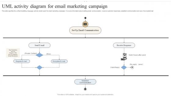
This slide signifies the unified modelling language activity model used for email marketing campaign. It covers information about setting email communication, receive customer responses, establish communication and use of encrypted mail. Introducing our UML Activity Diagram For Email Marketing Campaign set of slides. The topics discussed in these slides are Email Communication, Receive Response, Private Content. This is an immediately available PowerPoint presentation that can be conveniently customized. Download it and convince your audience.
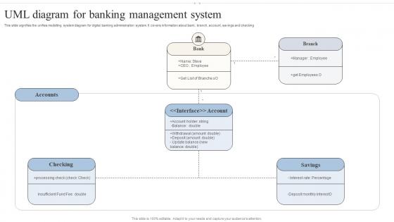
This slide signifies the unifies modelling system diagram for digital banking administration system. It covers information about bank, branch, account, savings and checking. Presenting our set of slides with UML Diagram For Banking Management System. This exhibits information on one stages of the process. This is an easy to edit and innovatively designed PowerPoint template. So download immediately and highlight information on Accounts, Bank, Savings.
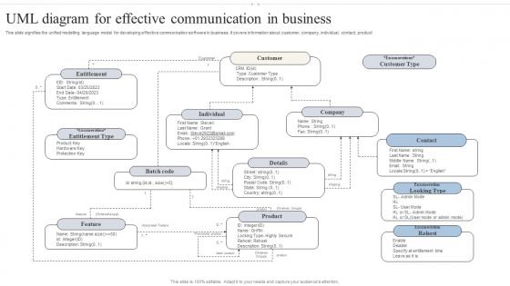
This slide signifies the unified modelling language model for developing effective communication software in business. It covers information about customer, company, individual, contact, product. Introducing our premium set of slides with UML Diagram For Effective Communication In Business. Ellicudate the one stages and present information using this PPT slide. This is a completely adaptable PowerPoint template design that can be used to interpret topics like Entitlement Type, Product, Feature. So download instantly and tailor it with your information.
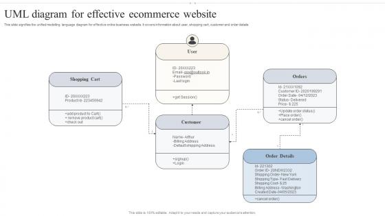
This slide signifies the unified modelling language diagram for effective online business website. It covers information about user, shopping cart, customer and order details. Presenting our set of slides with UML Diagram For Effective Ecommerce Website. This exhibits information on one stages of the process. This is an easy to edit and innovatively designed PowerPoint template. So download immediately and highlight information on Shopping Cart, Order Details, Orders.
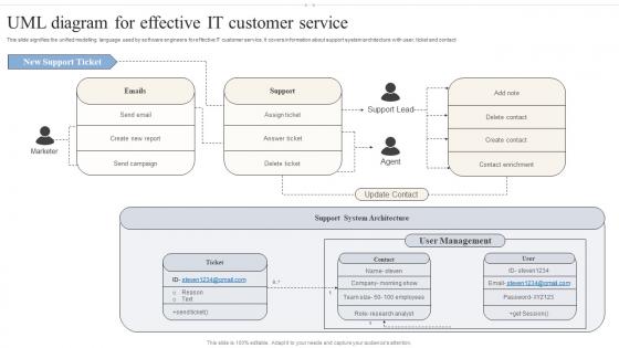
This slide signifies the unified modelling language used by software engineers for effective IT customer service. It covers information about support system architecture with user, ticket and contact. Introducing our premium set of slides with UML Diagram For Effective It Customer Service. Ellicudate the one stages and present information using this PPT slide. This is a completely adaptable PowerPoint template design that can be used to interpret topics like New Report, Send Campaign, Support System Architecture. So download instantly and tailor it with your information.
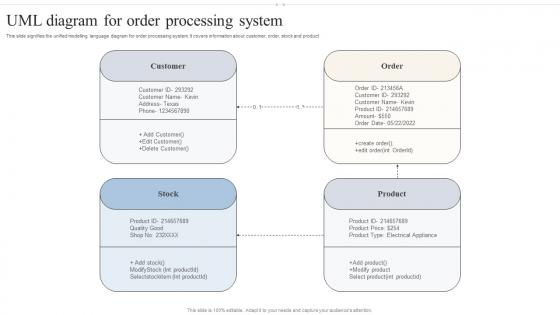
This slide signifies the unified modelling language diagram for order processing system. It covers information about customer, order, stock and product. Introducing our UML Diagram For Order Processing System set of slides. The topics discussed in these slides are Customer, Order, Modify Product. This is an immediately available PowerPoint presentation that can be conveniently customized. Download it and convince your audience.
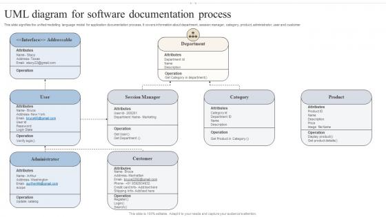
This slide signifies the unified modelling language model for application documentation process. It covers information about department, session manager, category, product, administrator, user and customer. Presenting our well structured UML Diagram For Software Documentation Process. The topics discussed in this slide are Department, Session Manager, Administrator. This is an instantly available PowerPoint presentation that can be edited conveniently. Download it right away and captivate your audience.
Presenting our set of slides with UML Diagram Icon For Effective Project Management. This exhibits information on three stages of the process. This is an easy to edit and innovatively designed PowerPoint template. So download immediately and highlight information on UML Diagram Icon, Effective Project Management.
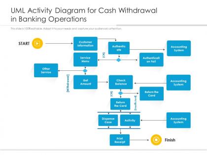
Presenting our well structured UML Activity Diagram For Cash Withdrawal In Banking Operations. The topics discussed in this slide are customer information, service menu, check balance, return the card, accounting system. This is an instantly available PowerPoint presentation that can be edited conveniently. Download it right away and captivate your audience.
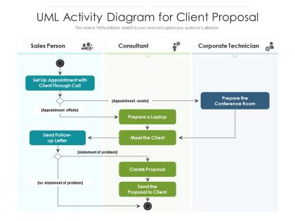
Introducing our premium set of slides with name UML Activity Diagram For Client Proposal. Ellicudate the three stages and present information using this PPT slide. This is a completely adaptable PowerPoint template design that can be used to interpret topics like sales person, consultant, corporate technician. So download instantly and tailor it with your information.
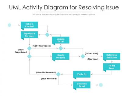
Presenting our well structured UML Activity Diagram For Resolving Issue. The topics discussed in this slide are reproduce the issue, determine resolution. This is an instantly available PowerPoint presentation that can be edited conveniently. Download it right away and captivate your audience.
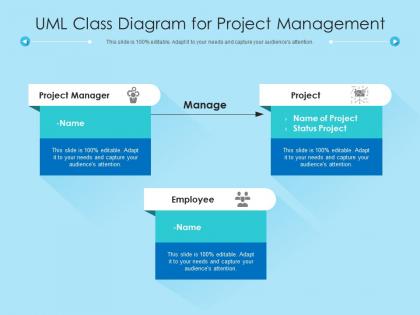
Introducing our UML Class Diagram For Project Management set of slides. The topics discussed in these slides are project manager, employee, manage. This is an immediately available PowerPoint presentation that can be conveniently customized. Download it and convince your audience.
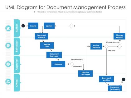
Introducing our premium set of slides with name UML Diagram For Document Management Process. Ellicudate the four stages and present information using this PPT slide. This is a completely adaptable PowerPoint template design that can be used to interpret topics like approver, reviewer, document drafted, document reviewed. So download instantly and tailor it with your information.


IMAGES
VIDEO
COMMENTS
By placing standard UML diagrams in your methodology's work products, you make it easier for UML-proficient people to join your project and quickly become productive. The most useful, standard UML diagrams are: use case diagram, class diagram, sequence diagram, statechart diagram, activity diagram, component diagram, and deployment diagram.
What is a UML Diagram? UML is a way of visualizing a software program using a collection of diagrams. The notation has evolved from the work of Grady Booch, James Rumbaugh, Ivar Jacobson, and the Rational Software Corporation to be used for object-oriented design, but it has since been extended to cover a wider variety of software engineering projects.
Unified Modeling Language (UML) Diagrams. Unified Modeling Language (UML) is a general-purpose modeling language. The main aim of UML is to define a standard way to visualize the way a system has been designed. It is quite similar to blueprints used in other fields of engineering. UML is not a programming language, it is rather a visual language.
Ave Coders! And welcome to the UML course for beginners. We will look into the most widely used diagrams, their basic notation, and applications. Each diagra...
UML diagrams can capture a wide variety of systems, from inventory systems to banking applications. UML diagrams are key communication tools to help you: Simplify large or complex systems. Technical and non-technical stakeholders can quickly grasp a product concept or app in development. Improve collaboration.
Use Case Diagram. As the most known diagram type of the behavioral UML types, Use case diagrams give a graphic overview of the actors involved in a system, different functions needed by those actors and how these different functions interact.. It's a great starting point for any project discussion because you can easily identify the main actors involved and the main processes of the system.
UML Diagrams are the output of the Unified Modeling Language. It is a pictorial representation of classes, objects, and relationships between them. UML diagram is a model that describes a part of a system. It is used to define the functionality or a design of a system. A diagram must be clear and concise so that the viewer will readily ...
UML is used to create static structure diagrams based on a variety of engineering practices that have proven to be successful in the creation of complex systems. The published standards are almost 800 pages long. Historically, UML has been used to model software systems, but it's not limited to software developers.
A UML diagram is the visual blueprint of software and business processes, using the Unified Modeling Language as its foundation. This diagram plays a pivotal role in object-oriented design, capturing the essence of both static structure and dynamic behavior within software systems. UML encompasses various diagram examples, each tailored to ...
Uml diagrams. Jan 01, 2020. 530 likes | 871 Views. Uml diagrams. In ooad. uml. UML is a standard language for specifying, visualizing, constructing, and documenting the artifacts of software systems. UML was created by the Object Management Group (OMG) and UML 1.0 specification draft was proposed to the OMG in January 1997. Download Presentation.
A UML diagram shows the unified visual presentation of the UML (Unified Modeling Language) system intending to let developers or business owners understand, analyze, and undertake the structure and behaviors of their system.. So far, the UML diagram has become one of the most common business process modeling tools, which is also highly significant to the development of object-oriented software.
UML diagrams can be incredibly helpful when you need to onboard employees or reference source code during implementation, but they become outdated quickly and take hours to build—unless you use a UML diagram tool like Lucidchart. We've compiled templates for three types of structural UML diagrams—class, component, and object diagrams—and ...
A UML diagram template is a tool you can use as a starting point for creating a customized UML diagram. It's a visual representation showing how parts of a program, system, or process work together. UML stands for Unified Model Language, which is a visual language with a specific set of rules used for drawing UML diagrams.
Component diagram. A UML component diagram maps the structural relationship of the components of software systems. It visually represents a system's components (with interfaces and ports) and the relationships between them. Detailed component diagrams make use of subsystems, which inherit the same rules as components.
When you are done, save the diagram. Create UML diagram in PowerPoint. PowerPoint is one of the popular presentation software which is commonly used by business people and students to create slides for presentations. in addition to that, users can add different content such as diagrams, pie charts, images, and other shapes and symbols.
UMLClass Diagrams: Basic Concepts Extracted from textbook: Object Oriented Modeling and Design with UML M. Blaha, J. Rumbaugh. Objects • The purpose of class modeling is to describe objects. • An object is a concept, abstraction or thing that has meaning for a domain/application. • Some objects have real world counterparts while others are conceptual entities.
Customize this template and make it your own! Edit and Download. To start a new diagram inside any project, use the / shortcut and scroll to the diagram icon and click or write 'diagram' in the search bar. Use this shortcut feature to find anything you want inside the editor quickly. 13.
Multi-Layered Application UML Model Diagram Example. An example of UML model diagram representing a model of a layered application, based on the Microsoft Application Achitecture Guide, 2nd Ed. According to the Guide, layers are concerned with the logical division of components and functionality, and do not take into account the physical location of components, whereas tiers describe the ...
To download UML Diagrams presentation templates, you can follow these steps: Select the resolution (16*9 or 4*3). Select the format you want to download the UML Diagrams template in (Google Slides or PowerPoint). Make the payment (SlideUpLift has a collection of paid as well as free UML Diagrams PowerPoint templates).
Slide 1 of 2. Uml class diagram for project management. Introducing our UML Class Diagram For Project Management set of slides. The topics discussed in these slides are project manager, employee, manage. This is an immediately available PowerPoint presentation that can be conveniently customized. Download it and convince your audience.