- Publications
- News and Events
- Education and Outreach

Software Engineering Institute
Cite this post.
AMS Citation
Shevchenko, N., 2020: An Introduction to Model-Based Systems Engineering (MBSE). Carnegie Mellon University, Software Engineering Institute's Insights (blog), Accessed April 24, 2024, https://insights.sei.cmu.edu/blog/introduction-model-based-systems-engineering-mbse/.
APA Citation
Shevchenko, N. (2020, December 21). An Introduction to Model-Based Systems Engineering (MBSE). Retrieved April 24, 2024, from https://insights.sei.cmu.edu/blog/introduction-model-based-systems-engineering-mbse/.
Chicago Citation
Shevchenko, Nataliya. "An Introduction to Model-Based Systems Engineering (MBSE)." Carnegie Mellon University, Software Engineering Institute's Insights (blog) . Carnegie Mellon's Software Engineering Institute, December 21, 2020. https://insights.sei.cmu.edu/blog/introduction-model-based-systems-engineering-mbse/.
IEEE Citation
N. Shevchenko, "An Introduction to Model-Based Systems Engineering (MBSE)," Carnegie Mellon University, Software Engineering Institute's Insights (blog) . Carnegie Mellon's Software Engineering Institute, 21-Dec-2020 [Online]. Available: https://insights.sei.cmu.edu/blog/introduction-model-based-systems-engineering-mbse/. [Accessed: 24-Apr-2024].
BibTeX Code
@misc{shevchenko_2020, author={Shevchenko, Nataliya}, title={An Introduction to Model-Based Systems Engineering (MBSE)}, month={Dec}, year={2020}, howpublished={Carnegie Mellon University, Software Engineering Institute's Insights (blog)}, url={https://insights.sei.cmu.edu/blog/introduction-model-based-systems-engineering-mbse/}, note={Accessed: 2024-Apr-24} }
An Introduction to Model-Based Systems Engineering (MBSE)

Nataliya Shevchenko
December 21, 2020.
This post has been shared 62 times.
Model-based systems engineering (MBSE) is a formalized methodology that is used to support the requirements, design, analysis, verification, and validation associated with the development of complex systems. In contrast to document-centric engineering , MBSE puts models at the center of system design. The increased adoption of digital-modeling environments during the past few years has led to increased adoption of MBSE. In January 2020, NASA noted this trend by reporting that MBSE, "has been increasingly embraced by both industry and government as a means to keep track of system complexity." In this blog post, I provide a brief introduction to MBSE.
One area of concern within complex systems is cybersecurity . The SEI CERT Division has begun researching how MBSE can be used to mitigate security risks early in the system-development process so that systems are secure by design , in contrast to the common practice of adding security features later in the development process. Capturing system attributes in models enables systems engineers to perform threat-modeling analysis of the system early and incorporate mitigation strategies into the system design, thereby reducing the system's overall security-related risks.
MBSE in a digital-modeling environment provides advantages that document-based systems engineering cannot provide . For example, in a document-based approach, many documents are generated by different authors to capture the system's design from various stakeholder views, such as system behavior, software, hardware, safety, security, or other disciplines. Using a digital-modeling approach, a single source of truth for the system is built in which discipline-specific views of the system are created using the same model elements.
A digital-modeling environment also creates a common standards-based approach to documenting the system that can be programmatically validated to remove inconsistencies within the models and enforce the use of a standard by all stakeholders. This common modeling environment improves the analysis of the system and reduces the number of defects that are commonly injected in a traditional document-based approach. The availability of digitalized system data for analysis across disciplines provides consistent propagation of corrections and incorporation of new information and design decisions (i.e., state it once and automatically propagate to various views of the data) to all stakeholders. When MBSE is done properly, the result is an overall reduction of development risks.
MBSE brings together three concepts: model, systems thinking, and systems engineering:
- A model is a simplified version of something--a graphical, mathematical, or physical representation that abstracts reality to eliminate some complexity . This definition implies formality or rules in simplifying, representing, or abstracting. To model a system, a systems architect must represent the system with less detail so that its structure and behavior are apparent and its complexity is manageable. In other words, models should sufficiently represent the system, and the system should confirm the model s.
- Systems thinking is a way of looking at a system under consideration not as a self-sufficient entity, but as part of a larger system. Systems thinking is not the same as a systematic adherence to following good plans, collecting statistics, or being methodical . The systems engineer observes the system from a distance; explores its boundaries, context, and lifecycle; notes its behavior; and identifies patterns. This method can help the engineer to identify issues (e.g., missing interaction, a missing step in a process, duplication of effort, missed opportunity for automation) and manage a system's complexity. Although systems engineers must break down and analyze the system in the beginning--identify parts and describe connections between them--with systems thinking, they later synthesize the parts back into a coherent whole. Parts are not just connected to other parts, they depend on each other to work properly. Systems thinking emphasizes this interconnectedness. The behavior of the system emerges from the activities of the system's subparts. Observing the system's interconnections, the systems engineer identifies feedback loops and causality patterns that may not be apparent at first . Systems thinking can help make issues more apparent and easier to identify, balance the system, and manage the system's complexity.
- Systems engineering is a transdisciplinary and integrative approach to enable the successful realization, use, and retirement of engineered systems , using systems principles and concepts, and scientific, technological, and management methods. It brings together a number of techniques to make sure that all requirements are satisfied by the designed system. It concentrates on architecture, implementation, integration, analysis, and management of a system during its lifecycle. It also considers software, hardware, personnel, processes, and procedural aspects of the system.
If an organization has decided to adopt MBSE as an internal systems-engineering approach and chosen one of the four or five existing products for digital modeling that are on the market, the organization's systems engineers should consider whether it is going to follow any architectural frameworks. Although a comprehensive discussion of this topic is beyond the scope for this blog post, the choice of a particular architectural framework will provide additional guidance and structure to the modeling activities, especially if the systems engineers are already familiar with the framework.
MBSE is a multidisciplinary and multifaceted endeavor. It requires its own actors, processes, environment, and information flows. To create a successful model of a complex system or system of systems , an organization must support the modeling process. The support needed is not much different from what is required for an organization to successfully develop and deliver a complex system or system of systems. MBSE can be effectively integrated into a development process, but the organization must commit to the effort that will be required to model the system.
Applying systems thinking, we can recognize that there are three systems involved in the modeling process : the designed system, the designed system's context, and the modeling organization for the designed system. The designed system operates in the context of a larger system, and the modeling organization must understand both the designed system and the designed system's context. The organization must also be aware of its own behavior, successes, and failures.
We have all seen, used, or created models throughout our lives, ranging from toys that represent cars or planes to mathematical formulas that describe and explain physical phenomena such as thermodynamics or gravity. While fundamentally different, those models all connect an idea to a reality and provide sufficient abstraction for the purpose . When modeling a system, the systems engineer decides what aspects of the production system are most important, such as structure, energy or matter flow, internal communication, or safety and security. Those types of aspects will become the focus of the model. The top objective of the modeling activity is to model the salient aspects on which the model is focused as closely to the real system as is possible and feasible.
Modeling as a technique uses four instruments :
- argumentation
- presentation
A modeling language is a common terminology for clearly communicating an abstract idea that the model captures. The modeling language can be formal, with strict syntax and rules. A few system-modeling languages exist, including general-purpose languages such as the Systems Modeling Language (SysML) and Unified Modeling Language (UML) , as well as specialized languages such as Architecture Analysis Design Language (AADL) . Although SysML and UML are not mathematically formal, a valid model requires that the modeling language's rules for entities and relationships be followed. SysML has strict syntax and rules for relationships and connections between elements, which helps to avoid ambiguity. If a model is well built, several types of standard SysML diagrams can be dynamically simulated, and at least one type of SysML diagram can be mathematically simulated. UML is semi-formal; SysML is similar to UML, but more formal .
A model must have a structure. A well-structured model can make the model understandable, usable, and maintainable, which is particularly important for complex systems. The goal of a model is to show stakeholders that the presented design satisfies the system's requirements. The model should demonstrate, in an easily comprehensible way, how the system must be built to be successful. Visualization is a key way to ensure comprehensibility. Visualizing abstract ideas enables people to take the leap of imagination that is needed to "see" the system.
Modeling Domains
Even though MBSE does not dictate any specific process, essentially any process chosen should cover four systems-engineering domains :
- requirements/capabilities
- architecture/structure
- verification and validation
Descriptions of these domains are well documented and discussed by, among others, Defense Acquisition University (DAU) , NASA , and Avi Sharma . The difference that MBSE makes is that these fundamental systems-engineering domains are defined not as a set of documents, but in the model itself, i.e., in a formal way using a modeling language. The model represents an argument for how the system must be designed for it to be successful.
MBSE also fosters communication among stakeholders, systems engineers, and developers. Since system design is performed in the integrated modeling environment, all systems engineers, managers, and other stakeholders can have access to the generated information--such as requirements, behavior flows, and architecture--as soon as necessary.
The most common modeling activity is the creation of diagrams representing some part of the system--a view. This activity is so common that some engineers mistakenly equate creating a view with creating a model. This mistake is so pervasive that there is even an emerging term for it: zombie model . This term refers to a model that is full of diagrams, but with no interconnectivity and dependencies identified among the elements.
Anyone who is about to start modeling must realize that a set of views is not a model. Although a view or even a set of views can represent a part of the system's design and can be useful for documenting and communicating some aspects of the system, views are only facets or portions of the true system model. A real model can produce many views and matrices, perform analyses, and run simulations.
Language of System Modeling
While a system-modeling language such as SysML is a formal syntactic language, it is still based on elements of human language. Its formality adds clarity and discipline that are critical for describing the design of a system. Such a language is easy to read and understand. Terms of MBSE's language simply map to parts of speech :
- noun: actors, blocks, components, requirements
- verb: operational activities, functions, use cases
- adjective: attributes
- adverb: relationships, needlines , exchanges, interfaces
This view of the modeling language helps its users to mentally map real-life concepts to abstract ideas, and eases the formalization of the modeling process.
Four Quadrants of the MBSE Model
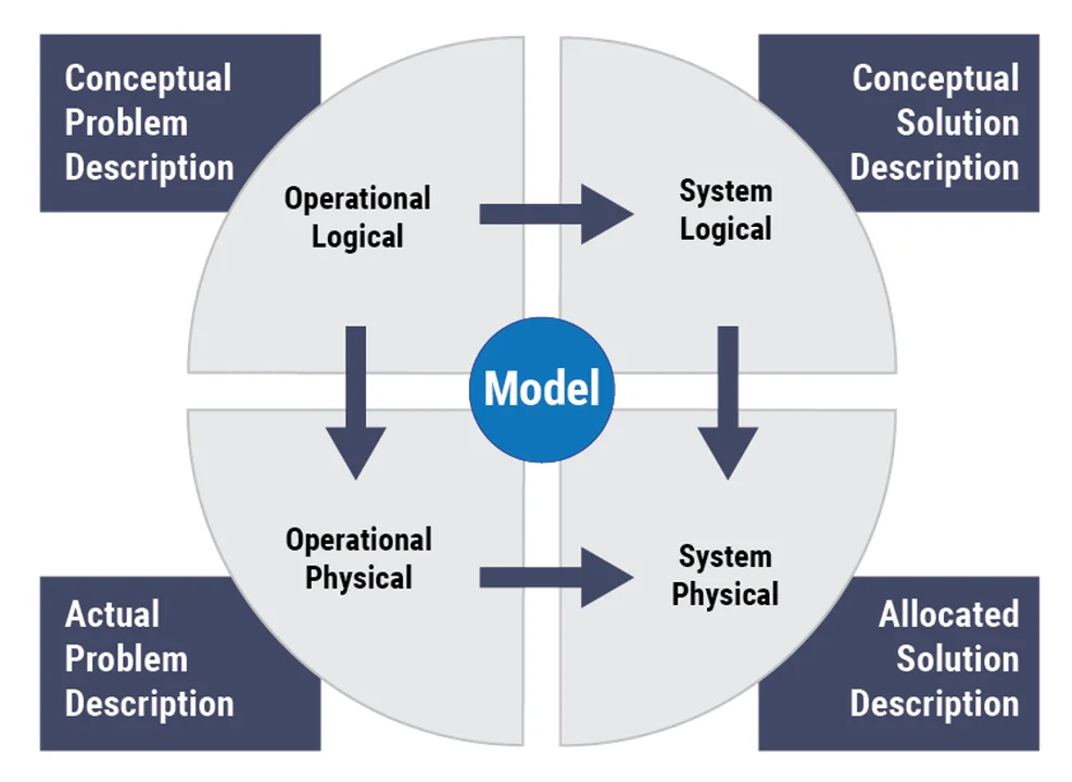
Now that I have described the basics of a model's language and domains, I will describe the modeling approach. A model must describe both a problem that the designed system solves, and the designed system itself (the solution). The model must have these two sides, the problem side and the solution side . These are sometimes referred to as the operational and system points of view.
The operational point of view is the perspective of users, operators, and business people. It should represent business processes, objectives, organizational structure, use cases, and information flows. The operational side of the model can contain the description of "the world as-is" and the future state.
The system point of view is the solution, the architecture of the system that solves the problem posed in the operational side of the model. It should describe the behavior of the system, its structure, dataflows between components, and allocation of functionality. It should describe how the system will be deployed in the real world. It can contain solution alternatives and analyses of them.
Each of these points of view has two parts, logical and physical. Separating logical and physical aspects of the model is a way to manage a system's complexity. Logical parts of the model usually change little over time, while physical changes are often initiated by technology advances.
If the model is built properly, all four quadrants should be tightly connected, as shown in Figure 1 below. Statements of the problem should be traced to elements of the solution, and logical elements allocated to physical structures. The user of the model should be able to see clearly how the top-level concepts and components decompose to the lower level features. Users should be able to perform system analysis, create dependency matrices, run simulations, and produce a view of the system for every stakeholder. If the physical part of the system must change, the logical side of the model identifies exactly what functionality will be affected. If a requirement or business process must be changed, the model will easily discover the impact on the solutions.
Wrapping Up and Looking Ahead
In this post, I explained what MBSE is, showed how it relates to systems engineering, and discussed the fundamentals of model and modeling. My next post will take a more practical approach and discuss requirements and requirements models.
Additional Resources
Watch the SEI video, What Would Convince DoD Program Managers to Use Model-Based System Engineering?
Read the SEI blog post, Modeling Capabilities with Model-Based Systems Engineering (MBSE)
Read the SEI blog post, Requirements in Model-Based Systems Engineering (MBSE)
Read the SEI blog post, Evaluating Threat-Modeling Methods for Cyber-Physical Systems .
Read the SEI blog post, Threat Modeling: 12 Available Methods .

Author Page
Digital library publications, send a message, more by the author, modeling capabilities with model-based systems engineering (mbse), november 28, 2022 • by nataliya shevchenko, a case study in applying digital engineering, april 18, 2022 • by nataliya shevchenko , peter capell, requirements in model-based systems engineering (mbse), february 22, 2021 • by nataliya shevchenko, evaluating threat-modeling methods for cyber-physical systems, february 4, 2019 • by nataliya shevchenko, threat modeling: 12 available methods, december 3, 2018 • by nataliya shevchenko, get updates on our latest work..
Sign up to have the latest post sent to your inbox weekly.
Each week, our researchers write about the latest in software engineering, cybersecurity and artificial intelligence. Sign up to get the latest post sent to your inbox the day it's published.
- Skip to main content
Action Engineering
Model-Based Enterprise Experts

Introduction to Model-Based Definition (MBD)
posted on August 7, 2018
Action Engineering has assembled a series of self-paced, online courses designed to advance the learning and adoption of the Model-Based philosophy across design and manufacturing sectors.
I am Duane Hess, CIO of Action Engineering and instructor for Course 102. This course provides an introduction and orientation to 3D Model-Based Definition (MBD) data sets and the purpose, application, and common practices for 3D Product and Manufacturing Information (PMI). You will also learn how MBD works in conjunction with GD&T and PMI.
Topics that will be covered and what you will learn in the Course 102 seven-part video:
- What is MBD: How to add MBD and handling data exchange for MBD.
- Different annotation types for models versus drawings, and best modeling and annotation practices.
- How MBD is different from drawings, review data exchange, and the definition of a derivative.
- Techniques to streamline preferred presentation methods, options for annotation authoring, and adherence to standards.
- A five-step process for adding MBD to a model, and nominal versus mean modeling.
- Methods to evolve your drawing-based practices into model-based product definition.
- Learn the basics of Geometric Dimensioning and Tolerancing (GD&T) rules to create 3D technical data sets for effective downstream consumption.
- Identifying key and product characteristics and how to identify them in the native CAD environment.
Video Overview: Course 102 – Intro to Model-Based Definition
Rent Now : Course 102 – Intro to Model-Based Definition
Some of the common questions we get from prospective students for Course 102 include:
Q: I don’t see any reference to the CAD software in use at my company. How can I be sure this course is relevant to the work I am doing? A: The requirements of Model-Based Definition are the same, regardless of the CAD system used, and MBD is CAD-agnostic. Each CAD system certainly has its unique strengths and weaknesses, but that level of detail is covered in other training courses. What is important to your MBD implementation is that everyone at your organization applies annotations (PMI) with consistency. If you are one of those companies that uses more than one CAD system, then this methodology is a must.
Q: We are already using CAD software to design parts and assemblies. I see that this course references GD&T – are there particular GD&T tools or software we should be using to benefit from this course? A: Each of the large CAD tools have their own GD&T authoring tools for MBD, as well as partner tools. While these tools greatly improve the user experience, they are not necessary for this course, which focuses on the fundamental principles of GD&T, and not so much the usage of the CAD tools.
Q: Would you recommend my team take this course even if other third-party vendors (like our suppliers) aren’t yet ready for MBD? A: Yes, absolutely. The evolution to Model-Based Definition needs to start somewhere. An understanding of MBD is necessary for all parties who interact with product data, including partners and suppliers outside the company. Wouldn’t you rather be the influencing catalyst directing your standards, processes, and procedures instead of having them defined for you?
Q: Our company has been designing products/parts for many years. Is it too late to start to incorporate MBD? A: It’s never too late! It also is not always necessary to redo all of your drawings to comply with MBD/MBE practices. It is best to start with a new project to apply MBD/MBE principles. The typical timeline for preparing your enterprise for MBD/MBE is 3 to 5 years that involves people, processes, standards, and tools for engineering, manufacturing, and inspection technology.
Q: Who are the ideal students for this course? What job roles would benefit most from this course? A: The students from this course should include not only engineering but also any downstream consumer of engineering design documents. This includes but is not limited to manufacturing, quality, inspection, and procurement.
Q: What learning materials are included in this course? A: The course is delivered online via on-demand video content. Students are provided with access to the content for a set period of time, even after the initial viewing of the course.
Q: Can we combine some of the courses to conduct a webinar with multiple members of our team present? Which courses would you recommend combining in such a multi-day program? A: We are often asked to bundle our 101, 102, and 108 courses together as a workshop. This set of courses can be delivered as a webinar or in a live classroom setting. These can also be combined with our other courses .
We hope this inspires you to invest in your continuing education by downloading Course 102. If you have any questions on this or any other MBD/MBE courses offered by Action Engineering, please contact us . We hope to see you as one of our online course registrants soon as you begin the journey for successfully implementing MBD and MBE.
Video Overview: Course 102 – Intro to Model-Based Definition
Rent Now : Course 102 – Intro to Model-Based Definition
- Skip to primary navigation
- Skip to main content
- Skip to primary sidebar
- Skip to footer
3D CAD World
Over 50,000 3D CAD Tips & Tutorials. 3D CAD News by applications and CAD industry news.
Five presentations on Model-Based Development
April 24, 2013 By Evan Yares Leave a Comment
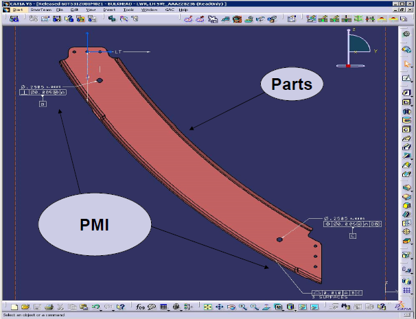
That’s probably a pretty good working definition, but it’s not really quite right. I went back to a 2010 U.S. Army Research, Development and Engineering Command presentation, and found a more complete definition:
A 3D annotated model and its associated data elements that fully define the product definition in a manner that can be used effectively by all downstream customers in place of a traditional drawing.
The central concept embodied in MBD is that the 3D product model is vehicle for delivery of all the detailed product information necessary for all aspects of the product life cycle. Any number of views of the model can be composed, detailed, and annotated for specific downstream operations including codification & classification, cost analysis, producibility analysis, process planning, assembly simulation, procurement, manufacturing, quality assurance, standards compliance, and many others.
The advantages of MBD can be compelling:
- Faster design revisions,
- Build and test components and assemblies in a virtual environment (do-overs are no problem),
- Infinite viewpoints and exploded views of assemblies,
- Direct to rapid prototyping,
- Direct to engineering analysis (stress, thermal, interference fit, tolerance stack-up, etc.),
- Reduced manufacturing lead time and cost,
- Automated generation and update of drawings (when drawings are needed), and
- Generation of technical manuals directly from model data.
Of course, with all those benefits, you can’t expect it to be easy to implement. There are both technical and cultural issues that have yet to be completely ironed out.
Rather than writing a long article on MBD, it occurs to me that it might make more sense not to reinvent the wheel. Last fall, I attended the Boeing/Northrop Grumman Global Product Data Interoperability Summit, where several people who spend most of their business days working on MBD (and the related concept of Model-Based Enterprise) gave some impressive presentations on the subject.
So, I give you five presentations on MBD:
I found each of these presentations to be informative, and thought provoking. If, by any chance, you too find the subject interesting, and would like to learn more, I’d like to suggest attending the 3D Collaboration and Interoperability Congress , May 21-23, in Colorado Springs, Colorado. Judging by this year’s agenda, it should be well worth the trip.
Reader Interactions
Leave a reply.
You must be logged in to post a comment.
This site uses Akismet to reduce spam. Learn how your comment data is processed .

DESIGN WORLD NETWORK
3d cad world.
- Subscribe to our newsletter
- Advertise with us
Model-Based Design Overview
Dec 19, 2019
200 likes | 211 Views
Model-Based Design Overview. Janos Sztipanovits and Gabor Karsai ISIS, Vanderbilt University. Model-Based Design. Model-based design focuses on the formal representation, composition, and manipulation of models during the design process. Core Modeling Aspects in System Composition.
Share Presentation

Presentation Transcript
Model-Based Design Overview Janos Sztipanovits and Gabor Karsai ISIS, Vanderbilt University
Model-Based Design Model-based design focuses on the formal representation, composition, and manipulation of models during the design process. "Model-Based Design Overview", J. Sztipanovits
Core Modeling Aspects in System Composition • Modeled on different levels of abstraction: • Transition systems (FSM, Time Automata, Cont. Dynamics, Hybrid), fundamental role of time models • Precise relationship among abstraction levels • Research: dynamic/adaptive behavior Component Behavior • Expressed as a system topology : • Module Interconnection (Nodes, Ports, Connections) • Hierarchy • Research: dynamic topology Structure • Describes interaction patterns among components: • Set of well-defined Models of Computations (MoC) (SR, SDF, DE,…) • Heterogeneous, but precisely defined interactions • Research: interface theory (time, resources,..) Interaction • Mapping/deploying components on platforms: • Dynamic Priority • Behavior guarantees • Research: composition of schedulers Scheduling/ Resource Mapping "Model-Based Design Overview", J. Sztipanovits
Tool Composition Approaches • Domain-Specific Design Flows andTool Chains: • ECSL - Automotive • ESML - Avionics • SPML - Signal Processing • CAPE/eLMS Domain-Specific Tools;Design Environments • MIC Metaprogrammable Tool Suite:(mature or in maturation program) • Metamodeling languages • Modeling Tools • Model Transformations • Model Management • Design Space Construction and Exploration • Tool Integration Framework Metaprogrammable Tools, Integration Frameworks • Semantic Foundations (work in progress): • Semantic Anchoring Environment (SAE) • Verification • Semantic Integration Semantic Foundation "Model-Based Design Overview", J. Sztipanovits
Metaprogrammable Tools, Environments Domain-Specific Tools, Tool Chains Semantic Foundation; Intersection with Tool Composition Dimensions Component Behavior Semantic Units and Semantic Anchoring Metamodels and Metaprogrammable Tool Suites Domain-Specific Design Flows and Tool Chains Compositional Semantics Structure Interaction Resource Modeling(Schedule) "Model-Based Design Overview", J. Sztipanovits
Domain Specific Design Flows and Tool Chains • ECSL - Automotive • ESML - Avionics • SPML - Signal Processing • FCS – Networked Embedded Systems • CAPE/eLMS – Courseware Design/Delivery • Integration among tool frameworks:Metropolis, Ptolemy II, MIC, Simulink/Stateflow, ARIES, CheckMate,… • www.escherinstitute.org "Model-Based Design Overview", J. Sztipanovits
OTIF Component Abstraction (TA) Design Space Modeling (MD) Design Space Encoding (TE) Component Reconstruction Design Decoding Design Space Pruning Metaprogrammable Tool Suite Generic Model Editor (GME) GME Unified Data Model (UDM) Design Space Exploration (DESERT) UDM • Simulators • Verifiers • Model Checkers • Generators DESERT Meta Models Open Tool IntegrationFramework GReAT Model Transformation "Model-Based Design Overview", J. Sztipanovits
MS= MSi ○MA DSML S C DSML MC MS MOFADSMLi MTLTDSML,DSMLi MOFADSMLi A MA MOF MOF UMT Mi: MOFADSMLMOFADSMLi Transformational Specification of Semantics DSML i Ci Si Transformation T DSMLi MSi: AiSi MCi MSi Ai • Specify mapping to another language with well-defined semantics. "Model-Based Design Overview", J. Sztipanovits
Semantic Unit i MS= MSi ○MA DSML S C Ci Si Transformation T DSML DSMLi MSi: AiSi MCi MC MSi MS MOFADSMLi MTLTDSML,DSMLi MOFADSMLi A Ai MA MOF MOF UMT Mi: MOFADSMLMOFADSMLi Semantic Units • Ongoing Work • Capture the behavioral semantics of a finite set of basic models of computations, such as FSM, DE, TA, SDF… • Further exploration of the concept of abstract semantics with Berkeley. "Model-Based Design Overview", J. Sztipanovits
Semantic Anchoring Tool Suite Formal Framework for Semantic Units Specification Metamodeling and Model Transformation Tools GME Toolset GReAT Tool AsmL Tools Semantic Unit Spec. Model Checker Operational Semantics Spec. Abstract Data Model Semantic Unit Metamodel (Ai) DSML Metamdoel (A) Model Trans. Rules (MA) Test Case Generator Mc Generate Instance Instance Transformation Engine Data Model Domain Model (C) Domain Model (Ci) XSLT ASM Semantic Framework Model Simulator • Abstract State Machine (ASM) (Evolving Algebras) • AsmL tool suite • Metaprogrammable tools • Syntactic manipulations "Model-Based Design Overview", J. Sztipanovits
DSML Design Through Semantic Anchoring • Ongoing Work • Specification of component interaction semantics (MoC-s) • Design of a DSML Specification Environment • Compositional Semantics (with Berkeley and J. Sifakis, Verimag) Semantic Unit i MS= MSi ○MA DSML S C Ci Si Transformation T DSML SUi MSi: AiSi MCi MC MSi MS A Ai MA MOFADSMLi MTLTDSML,SUi MOFASUi MOF MOF UMT Mi: MOFADSMLMOFASUi "Model-Based Design Overview", J. Sztipanovits
Source Models Global “spaces” for Transformations Global spaces hold intermediate results of the transformation Consequence: The transformations are simplified. Global space <<Temps>> Sorting the transformation results A transformation rule typically operates on a sequence of matched objects that could be sorted after the rule is applied. Consequence: Model transformation results are ordered by the sorting function. sort():… Target Model DS-PI Model DS-PI Model DS-PS Model DS-PS Model Progress in Model Transformations: GReAT • GReAT Application Examples: • Embedded system toolchains (see ESCHER) • Large-scale architecture modeling and analysis tool for distributed embedded systems • Semantic anchoring framework for domain-specific modeling languages • Model-based tools for CORBA component configuration • Additional new capabilities: • Distinguished cross-product: a new built-in operator of the language that refines pattern matching semantics • Match-any associations: “wild-card” pattern matching construct for matching arbitrary associations • User code libraries • Support for automatic connection of multi-ported objects in the modeling tool • Integration with new development platform (Microsoft VS 7+) • Support for XML namespaces • Integration with Java in the data layer (UDM) • Support for text output (UDM, using OCL for scripting) • Support for structured text input: input is parsed using a declarative parser that constructs the input data structures "Model-Based Design Overview", J. Sztipanovits
Model Transformations for Hard-Real Time Languages: Control System Problem Model Transformation “Program” GPS 20 Hz 1000 Hz ailerons pitch air data 1000 Hz yaw 1000 Hz rudder throttle pilot ctrl 500 Hz 200 Hz engine Proof of concept: A full “compiler” formally specified Time-triggered Model (Giotto) Schedule (E-code) Control system engineers model control problems as periodically triggered sensing, control calculation, and actuation actions, but traditional software implementations rarely comply with these strict requirements. Giotto (as a time-triggered language) and it’s the E-machine (as its execution platform) offers a solution to bridge the gap between design and implementation. A prototype model transformation tool shows how the complex transformation from Giotto to E-code can be implemented in terms of graph transformation operations. "Model-Based Design Overview", J. Sztipanovits
Source Domain Models Model for Platform -> Analysis Mapping Model Transformation Specification Target Model Metamodel of Source DSML DS-PI Model DS-PI Model DS-PS Model DS-PS Model Metamodel of Target (SYNTAX) Model Transformations in Toolchains:Platform Modeling & Analysis Model of Platform Analysis Tool: • Model in Analysis format • Domain models • Platform semantics • Platform properties for ANALYSIS GENERATION for EXECUTION PLATFORM Approach: Analysis must take into consideration platform’s operational semantics, i.e. model of computation. To make this possible, an explicit platform model is required that proscribes how the platform’s concepts are mapped into the concepts of the analysis language. This mapping defines the model transformation needed. "Model-Based Design Overview", J. Sztipanovits
Research on Model Transformations: Next steps • (Better) formal semantics of GReAT • Goal: Reasoning about transformations • Use: in semantic anchoring • Verification/certification of transformations • Proving that the generated output satisfies some interesting properties • Traceability • Generated artifacts must be traceable back to their origins • Model transformations for model evolution • Model management and engineering in large-scale embedded systems • Transformations in mixed-mode development • Model-based components with hand-written code • Experimentation with platform modeling and analysis • Event-driven and time-triggered platforms • Multiple analysis tools • Transformations “guided” by platform restrictions • Example: resource-constrained platforms may influence the transformation process • Using graph transformations for embedded component adaptation "Model-Based Design Overview", J. Sztipanovits
Further Presentations • Ethan Jackson: Coupled Interface Modules for Heterogeneous Composition • Kai Chen: A Semantic Unit for Timed Automata Based Modeling Languages • Tivadar Szemethy: Platform Modeling • Trevore Meyerowitz, Ethan Jackson: Integration of Metropolis with GME and DESERT "Model-Based Design Overview", J. Sztipanovits
- More by User

Model-Based Safety Analysis Overview
Model-Based Safety Analysis Overview. Dr. Steven P. Miller Dr. Mats P. E. Heimdahl Advanced Computing Systems Rockwell Collins 400 Collins Road NE, MS 108-206 Cedar Rapids, Iowa 52498 [email protected]. Outline of Presentation. Motivation Proposed Approach Demonstration
1.21k views • 49 slides
Model-based design for decision making
Model-based design for decision making. Bergseth E ., Söderberg A ., Sellgren U., Möller B ., Wahlström J. and Johansson K.* KTH Machine Design & *Scania. Scholarship of Teaching and Learning March 16, 2017. What is a model ?. F = ma. Model.
525 views • 21 slides
Chp 1: Consumption-based model and overview
Chp 1: Consumption-based model and overview. 郑振龙 厦门大学金融系 个人网站: http://efinance.org.cn EMAIL: [email protected]. Structure. Basic Pricing Equation Stochastic Discount Rate Prices and Payoffs Classic Issues in Finance Discount Factors in Continuous time. Investors’ Utility Function .
717 views • 52 slides
Model Based Design of Embedded Systems
2. Outline. Introduction and MotivationConventional Design ApproachModel-based MethodologyRequirements Driven Test Scenario GenerationTool Support Summary. 3. Goals and Contributions. Establish a framework for model-based design of embedded systemsDefined embedded systems design as a systems m
407 views • 15 slides

Model-Based Controller Design
Model-Based Control. PID controller tuningRestrict controller to PID form Seek best" tuning parametersCan be perform with FOPTD model if availableModel-based controller designController is not restricted to PID formRequires a process model that is used to determine the controller form as well
447 views • 19 slides

Model-Based Design: an instance
Model-Based Design: an instance. Stavros Tripakis Cadence Berkeley Labs Talk at EE249, Nov 2006. design. implementation. Model based design: what and why?. Application. Stateflow. UML. …. Simulink. single-processor single-task. CAN. multi-processor TTA. single-processor
914 views • 71 slides
Model based Design : a firmware perspective
Model based Design : a firmware perspective. …yes, including the CASPER tool-flow. Raj Thilak Rajan [email protected] ASTRON. Raj Thilak Rajan Uni-Board FP7 Kickoff meeting Friday, February 27, 2009. Legacy+ IP cores. Specifications. Manual Coding. Verification. FPGA. RTL Synthesis.
175 views • 8 slides
Model-based hybrid reaction-separation process design
Model-based hybrid reaction-separation process design. P . T. Mitkowski , G. Jonsson, R. Gani Funded by PRISM (EC) CAPEC Department of Chemical Engineering Technical University of Denmark. Outline. Motivation & Objectives Methodology Case study Conclusion On going work…. Motivation.
376 views • 18 slides

Model-Based Design of Embedded Systems
MotoHawk Training. Model-Based Design of Embedded Systems. Course Outline. Why Model-Based Design? The MotoHawk ™ System w/ Demonstration The Simulink ® Model The MotoHawk ™ Way Advanced Software & Hardware Issues Real Application Challenge. Model-Based Design. Hand-Coding.
1.04k views • 46 slides
Updates to Table Linkbase Model-based Overview
Updates to Table Linkbase Model-based Overview. 16th Eurofiling Workshop 12 December 2012 Herm Fischer Rendering Working Group (Models by Jon Siddle , CoreFiling ). What is Table Linkbase ?. Abstract model for viewing (~presentation) Implementation of tables and form
296 views • 19 slides
Model-Based Design
Model-Based Design. Edited and Presented by Janos Sztipanovits, Co-PI ISIS, Vanderbilt University. Model-Based Design. Model-based design focuses on the formal representation, composition, and manipulation of models during the design process. Domain Specific Modeling Languages (DSML).
609 views • 37 slides

Model-Based Design & Analysis
Model-Based Design & Analysis. Dr. Steven P. Miller Advanced Computing Systems Rockwell Collins 400 Collins Road NE, MS 108-206 Cedar Rapids, Iowa 52498 [email protected]. What Problem are We Solving?. Safety-Critical Software Is Too Expensive
787 views • 52 slides
Model-Based Controller Design. Introduction Direct synthesis method Internal model control (IMC) IMC derived PID tuning rules Simulink example. Model-Based Control. PID controller tuning Restrict controller to PID form Seek “best” tuning parameters
1.37k views • 19 slides

354 views • 20 slides

Meta-model based system design
Meta-model based system design. G ábor Privitzky Gabor.Privitzky @ericsson.com Gábor Zsolt Nagy Gabor. [email protected]. Table of contents. Today’s software design Analysis and design Elaboration modeling approach Meta-models Translation modeling approach
561 views • 45 slides
COTS Based Systems (CBS) Cost Model Overview
COTS Based Systems (CBS) Cost Model Overview. Modeling Concept. Based on CBS activities: Use parametric models to estimate activity effort and schedule that have variability Use averages to estimate activities that are relative constant in effort and schedule Activities are described in
164 views • 11 slides

534 views • 52 slides

540 views • 49 slides

Model based design
Model based design. Objective. The interactive system design consisting of several stages such as Requirement Specification Design Prototyping Evaluation The interactive system design is highly iterative. scenarios task analysis. guidelines principles standards.
152 views • 13 slides

462 views • 45 slides
Model-Based Design and SDR
Model-Based Design and SDR. Fabio Ancona Sundance Italia SRL CEO – Sales Director. Model-Based Design. Designing complex systems needs new design methodologies: Binary coding. Assembly coding. C programming. Model-Based Designing. Aim of Model-Based Design.
323 views • 30 slides

382 views • 37 slides
- Presentation On Model Based Design Approach For Automotive Applications
Presentation on model-based design approach for automotive applications
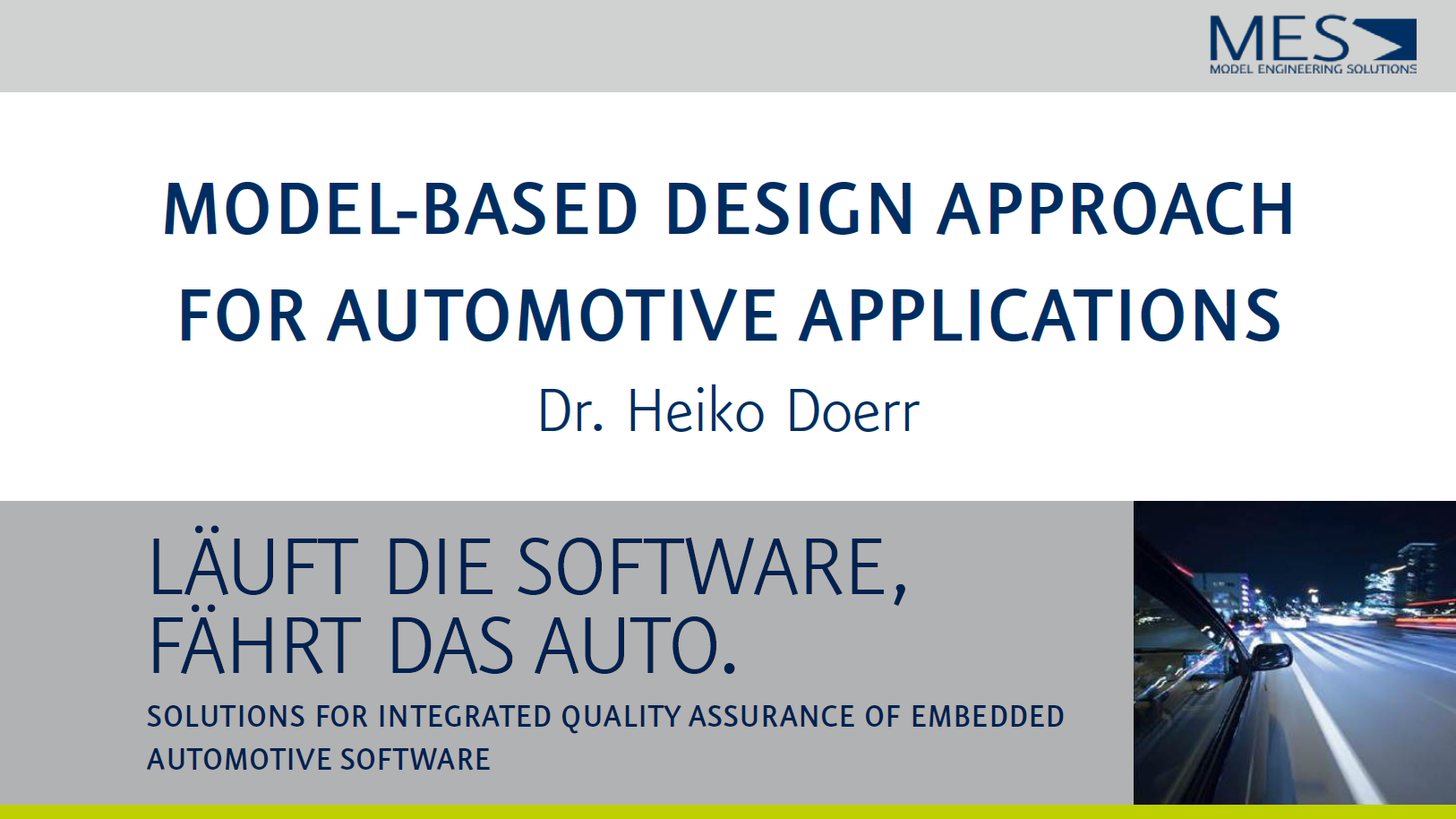
Learn more about model-based design with this exclusive presentation by Heiko Doerr, Managing Director from Model Engineering Solutions GmbH in Germany on the topic: "Model-based design approach for automotive applications".
Download the presentation for free here.
Please note: That all fields marked with an asterisk (*) are required.
This site is protected by reCAPTCHA and the Google Privacy Policy and Terms of Service apply.
*Processing your payment may take a moment. Please click submit payment only once, and do not refresh this page. Doing so may result in your credit card being charged more than once.
- Technical Articles
Best Practices for Implementing Modeling Standards Enterprise-Wide
By Michael Burke, MathWorks
Large engineering organizations in automotive, aerospace, and other industries can amplify the benefits of Model-Based Design by implementing modeling standards across their teams. High-integrity guidelines, including IEC 61508-3 and MISRA-C AC, strongly recommend the adoption and enforcement of modeling standards because of their numerous advantages. Models built with well-defined standards have a consistent visual presentation that makes them easier to read and understand. Such models have uniform interfaces, reducing integration problems and making it easier to share designs. Modeling standards also help ensure consistent code generation, model behavior, and traceability.
This article outlines best practices for adopting modeling standards and deploying them across an organization.
Establishing a Modeling Standards Team
The successful adoption of modeling guidelines, like any process, requires a core group responsible for managing each phase of the process and seeing the work through to completion. An extended team reviews the core team’s recommendations, gathers metrics on the deployment, and reports on experiences with the process, both positive and negative, so that issues can be identified and resolved.
The ideal core team has at least three members and includes individuals from each engineering group that uses Model-Based Design within the company. It is best to select individuals who have at least five years of experience with Model-Based Design.
Selecting Guidelines
Begin the adoption process by reviewing the existing guidelines for Model-Based Design. The primary industry sources are the MathWorks Automotive Advisory Board (MAAB) Style Guidelines , the NASA Orion Guidelines , and the Simulink Modeling Guidelines for High-Integrity Systems . Guidelines covering efficient code generation, the design of high-integrity systems, and standards such as DO-178B and IEC 61508 (ISO 26262) are available on mathworks.com.
While the MAAB guidelines were developed by an independent board of automotive OEMs and suppliers, companies outside the automotive industry use them to improve collaboration among internal teams and with partners.
The Orion Guidance, Navigation, and Control MATLAB and Simulink standards were developed by a team of NASA engineers and contractors who updated and expanded the MAAB guidelines as needed for the NASA Orion program. The MAAB Style Guidelines version 3.0 incorporates a subset of the original Orion rules. Simulink Modeling Guidelines for High-Integrity Systems were developed to help engineers create Simulink ® models that are complete, unambiguous, robust, and verifiable.
Customizing Guidelines
Once you have selected a basic set of guidelines, the next step is to modify and extend them to fit the specific needs of your organization. You can customize the MAAB guidelines by selecting specific implementations when the MAAB guideline provides options (as in rule NA_0005) or by adding specific detail when the rule provides general guidelines (for example, by specifying a compiler for rule NA_0026). Customization also involves defining basic standards, such as where labels should be displayed on signals (as covered by MAAB rule na_0005). In addition, your core team can create new rules to address workflow issues not addressed by the industry standard.
Deploying the Guidelines
It is best to deploy your custom modeling guidelines in phases, incorporating feedback from a subset of users before deploying the standards to larger groups, as follows:
Phase 1: Trial adoption. A group of approximately six to ten people begins applying guidelines to their models. This small group monitors how frequently guideline violations occur and reports any difficulties encountered in conforming to the guidelines. This phase typically lasts from one to three months.
Phase 2: Adjustment. Based on the feedback from Phase 1, the core team updates the guidelines. Updates can include rewriting guidelines to improve clarity, changing the priority, and delaying deployment of specific guidelines. This phase can be started as soon as initial feedback is available from Phase 1.
Phase 3: First targeted deployment. After adjustment, the guidelines are deployed to a larger group and used by that group throughout the project.
Phase 4: Project evaluation. At the completion of the first project (or after one year of deployment) the core team performs a post-mortem on the deployment process, analyzing the number and type of violations detected and commonly encountered issues.
In addition to following this phased deployment approach, the core team must obtain buy-in from end users. Acceptance is most likely when the end users see value in using the guidelines and when the guidelines impose minimal disturbance to their normal workflow.
Your team will be better able to obtain buy-in and minimize workflow disruptions if they take the following steps:
- Provide background information for each guideline that explains the problem that the guideline is designed to address.
- Provide automatic tools wherever possible to reduce or eliminate the burden of guideline checking for end users—the Model Advisor in Simulink can be used to automate the checking of built-in guidelines, and Simulink Check™ can be used for custom guidelines.
- Enforce guidelines only in the relevant stage of development—enforcement should be more lenient during initial development, becoming stricter as the code nears on-target deployment.
- Provide an exception mechanism for use when deviation from a guideline is unavoidable or necessary—for example, allow engineers to use the Model Advisor Exclusion Editor to exclude individual blocks from specific guideline checks (Figure 1).

Implementing_Modeling _fig1_w.jpg
Enforcing conformance to guidelines.
Conformance to guidelines can be enforced using an automated checking tool such as the Model Advisor. Enforcement is generally most effective if your organization requires guideline checks as a gateway for certain tasks in the development workflow—for example, if engineers are required to check their models for compliance before they check the models into a configuration management system or generate code. You may decide to relax enforcement of certain guidelines during initial development, requiring engineers to follow those guidelines only in later development stages. Enforcement of some guidelines may be stricter for fixed-point projects or high-integrity projects and more relaxed for projects that involve legacy modules.
Reports are the primary mechanism for enforcing guidelines. Reporting serves an immediate purpose in providing feedback to the engineer (Figure 2), and a long-term benefit in enabling the core team to determine which guidelines are causing the most problems. On high-integrity projects, the reports may be checked into the configuration management system with the model and maintained as a development artifact.

Implementing_Modeling _fig2_w.jpg
Acquiring feedback.
Soliciting and responding to feedback is essential to the successful adoption of modeling standards. Ensure that your engineering team has a simple way to provide feedback from the project evaluation phase on. There is no need for a formal evaluation process; a simple email or web form is often sufficient. Ideally, the core team responds to all feedback, either by adjusting the guidelines or by clearly explaining why the guidelines were left unchanged. The process of acquiring and addressing feedback should be repeated periodically to ensure continued improvement and ongoing compliance.
About the Author
Michael Burke is a MathWorks principal technical consultant with 19 years of industry experience focusing on the analysis of workflows for Model-Based Design, hardware-in-the-loop systems, and testing strategies. For the last eight years, Michael has lead the NA-MAAB style guidelines working group and has been active in the development of MISRA-C compliance documentation. He holds B.S.A.E. and M.S.A.E. degrees from Virginia Polytechnic Institute.
Published 2014 - 92228v00
Products Used
- Simulink Check
MathWorks Automotive Advisory Board (MAAB) Style Guidelines
- NASA Orion Guidelines
Simulink Guidelines for High-Integrity Systems
- Model-Based Design Process Assessment and Maturity Framework
View Articles for Related Capabilities
- System Design and Simulation
- Embedded Code Generation
- Verification, Validation, and Test
View Articles for Related Industries
- Aerospace and Defense
Select a Web Site
Choose a web site to get translated content where available and see local events and offers. Based on your location, we recommend that you select: .
You can also select a web site from the following list
How to Get Best Site Performance
Select the China site (in Chinese or English) for best site performance. Other MathWorks country sites are not optimized for visits from your location.
- América Latina (Español)
- Canada (English)
- United States (English)
- Belgium (English)
- Denmark (English)
- Deutschland (Deutsch)
- España (Español)
- Finland (English)
- France (Français)
- Ireland (English)
- Italia (Italiano)
- Luxembourg (English)
- Netherlands (English)
- Norway (English)
- Österreich (Deutsch)
- Portugal (English)
- Sweden (English)
- United Kingdom (English)
Asia Pacific
- Australia (English)
- India (English)
- New Zealand (English)
Contact your local office
- Contact sales
- HTML Janos Sztipanovits. <a href="http://chess.eecs.berkeley.edu/pubs/144.html" ><i>Model-Based Design</i></a>, Talk or presentation, October, 2006.
- Plain text Janos Sztipanovits. "Model-Based Design". Talk or presentation, October, 2006.
- BibTeX @presentation{Sztipanovits06_ModelBasedDesign, author = {Janos Sztipanovits}, title = {Model-Based Design}, month = {October}, year = {2006}, abstract = {Presentation at NSF Fourth Year ITR Review (CHESS)}, URL = {http://chess.eecs.berkeley.edu/pubs/144.html} }
Posted by Mary Stewart on 12 Oct 2006. Groups: chess For additional information, see the Publications FAQ or contact webmaster at chess eecs berkeley edu.
Notice : This material is presented to ensure timely dissemination of scholarly and technical work. Copyright and all rights therein are retained by authors or by other copyright holders. All persons copying this information are expected to adhere to the terms and constraints invoked by each author's copyright.

IMAGES
VIDEO
COMMENTS
Model based development (MBD) Oct 21, 2013 • Download as PPTX, PDF •. 6 likes • 7,018 views. Shashi Kumar Mergu. A brief introduction to Model Based Design Process for all Automotive Engineers. Automotive Technology Business. 1 of 11. Download now. Model based development (MBD) - Download as a PDF or view online for free.
Explore Simulink, an environment for multidomain simulation and Model-Based Design for dynamic and embedded systems. Through product demonstrations, you will see a high-level overview of the major capabilities and how you can use Simulink to design, simulate, implement, and test a variety of time-varying systems, including communications, controls, signal processing, video processing, and ...
The Eurocopter EC130 helicopter. "We use our system design model in Simulink for ARP4754 to establish stable, objective requirements. We save time by using the model as the basis for our software design model for DO-178—from which we generate flight code—and reusing validation tests for software verification.".
Model-Based Design. Edited and Presented by Janos Sztipanovits, Co-PI ISIS, Vanderbilt University. Model-Based Design. Model-based design focuses on the formal representation, composition, and manipulation of models during the design process. Domain Specific Modeling Languages (DSML). 609 views • 37 slides
˜ Documentation, Presentation 10.12.2010 Model‐based Design 16. Key steps in the MBD approach (1) System identification (modeling the plant) is an iterative process. By acquiring and processing raw data from a real-world system and choosing a mathematical model to
Model-based systems engineering (MBSE) is a formalized methodology that is used to support the requirements, design, analysis, verification, and validation associated with the development of complex systems. In contrast to document-centric engineering, MBSE puts models at the center of system design.The increased adoption of digital-modeling environments during the past few years has led to ...
Flexible PC-based platform with environment-specific MCAL. Interfaces for I/O, Network access, Measurement & Calibration. Same AUTOSAR "SW under test" in all environments. Function under test as well the rest of functions in AUTOSAR environment. Uniform test environment for PC, Real Time. PC or ECU. Model Based Design approach for ...
Model-Based Design is the systematic use of models throughout the development process that improves how you deliver complex systems. You can use Model-Based Design with MATLAB and Simulink to shorten development cycles and reduce your development time by 50% or more. Try new ideas and perform fast repeatable tests with modeling and simulation.
The presentations from the Model-based Design Conference held jointly by MathWorks and the California State University on August 19, 2022. The objective of t...
What. Model-based systems engineering (MBSE) is the formalized application of modeling to support system requirements, design, analysis, verification and validation activities beginning in the conceptual design phase and continuing throughout development and later life cycle phases. A model is an approximation, representation, or idealization ...
Model-based design ( MBD) is a mathematical and visual method of addressing problems associated with designing complex control, [1] signal processing [2] and communication systems. It is used in many motion control, industrial equipment, aerospace, and automotive applications. [3] [4] Model-based design is a methodology applied in designing ...
Terminology. "Model-Based Engineering (MBE): An approach to engineering that uses models as an integral part of the technical baseline that includes the requirements, analysis, design, implementation, and verification of a capability, system, and/or product throughout the acquisition life cycle.". "Model-based systems engineering (MBSE ...
Action Engineering has assembled a series of self-paced, online courses designed to advance the learning and adoption of the Model-Based philosophy across design and manufacturing sectors. I am Duane Hess, CIO of Action Engineering and instructor for Course 102. This course provides an introduction and orientation to 3D Model-Based Definition (MBD) data sets and the […]
So, I give you five presentations on MBD: Bryan R. Fischer/. Phil Farcy. Advanced Dimensional Management / Boeing. How PMI and Data Modeling Standards Affect Successful Implementation of 3D MBD/MBE. Chris Garcia. Anark. Cost Effective Deployment of PLM & 3D MBD Data.
Dec 19, 2019. 200 likes | 208 Views. Model-Based Design Overview. Janos Sztipanovits and Gabor Karsai ISIS, Vanderbilt University. Model-Based Design. Model-based design focuses on the formal representation, composition, and manipulation of models during the design process. Core Modeling Aspects in System Composition. Download Presentation.
Learn more about model-based design with this exclusive presentation by Heiko Doerr, Managing Director from Model Engineering Solutions GmbH in Germany on the topic: "Model-based design approach for automotive applications". Download the presentation for free here.
History General Systems Theory (GST) was the fundamental underpinning of most commercial software design techniques by the 1970s Computer-Aided Software Engineering (CASE) tools developed in the 1980s Creating the Unified Modeling Language (UML) in the 1990s Model Driven Architecture (MDA) launched in 2001 10.12.2010 Model‐based Design 3
A design change oriented model-based definition ... For example, it indicates the type and presentation of drawing annotations for inclusion in the MBD dataset, however, it lacks to mention which MBD data set document format or template is to be adopted. 1 Another example is the incomplete PMI coverage by STEP format.
There is an ever-increasing need to reduce ECU production development cost, enhance quality, and shorten the development cycle time. Model-Based Design seems to play a key role in achieving the above results. This presentation focuses on the main components in a Model-Based Design framework and factors to be considered when an organization ...
The benefits around Model-based Definition are really significant. Companies are embracing the use of the PMI within that strategy, and they're seeing benefits in the area of time, cost, and quality. By enabling that model as the single source of truth, product teams are able to save valuable time by incorporating the product and process ...
NX Design and Characteristics Data Model What is it Characteristic -- A trait, quality, or attribute on an element of a feature such as its size, location, form, or property, which may be a specification limit, a dimension with tolerance etc. Bill of Characteristics -- a list of all the characteristics applied to a product Types
Begin the adoption process by reviewing the existing guidelines for Model-Based Design. The primary industry sources are the MathWorks Automotive Advisory Board (MAAB) Style Guidelines, the NASA Orion Guidelines, and the Simulink Modeling Guidelines for High-Integrity Systems.Guidelines covering efficient code generation, the design of high-integrity systems, and standards such as DO-178B and ...
Model-Based Design Janos Sztipanovits. Citation Janos Sztipanovits. "Model-Based Design". Talk or presentation, October, 2006. Abstract Presentation at NSF Fourth Year ITR Review (CHESS) Electronic downloads. 1030Model-BasedDesign-Janos.pdf · application/pdf · 1253 kbytes;